Cirkit Designer Logo
Cirkit Designer
Your all-in-one circuit design IDE
Home / 
Component Documentation

How to Use STEPPER DRIVER: Examples, Pinouts, and Specs

Image of STEPPER DRIVER
Cirkit Designer LogoDesign with STEPPER DRIVER in Cirkit Designer

Introduction

A stepper driver is a crucial electronic device used to control stepper motors, which are motors that move in discrete steps. They are commonly used in precision positioning systems such as 3D printers, CNC machines, and robotics. Stepper drivers receive input signals from a controller, such as a microcontroller or a computer, and amplify these signals to drive the stepper motor with the required current to move to the desired position.

Explore Projects Built with STEPPER DRIVER

Use Cirkit Designer to design, explore, and prototype these projects online. Some projects support real-time simulation. Click "Open Project" to start designing instantly!
Arduino-Controlled Stepper and DC Motor with Relay Switching
Image of Conveyor Belt & Capping Motor: A project utilizing STEPPER DRIVER in a practical application
This circuit controls a Nema 17 stepper motor using a DRV8825 driver module, with an Arduino UNO microcontroller dictating the step and direction. Additionally, the circuit can switch a DC motor on and off using a relay module controlled by the Arduino. The power supply provides the necessary voltage for the relay and the motor driver, which in turn powers the stepper motor, while the Arduino's firmware defines the motor's stepping behavior and the relay's switching to control the DC motor.
Cirkit Designer LogoOpen Project in Cirkit Designer
Arduino-Controlled Stepper Motor with LCD Interface and Rotary Encoder
Image of AC Servo Motor: A project utilizing STEPPER DRIVER in a practical application
This circuit is designed to control a bipolar stepper motor using an Arduino Mega 2560 microcontroller and a STEPPERONLINE DM542T driver. The Arduino interfaces with a 20x4 LCD display over I2C for user feedback, a membrane matrix keypad for user input, and a rotary encoder for precise control inputs. The power supply provides the necessary voltage and current to drive the stepper motor through the DM542T driver.
Cirkit Designer LogoOpen Project in Cirkit Designer
ATmega328P Microcontroller-Driven Stepper Motor with DRV8825
Image of Shutter for laser: A project utilizing STEPPER DRIVER in a practical application
This circuit is designed to control a bipolar stepper motor using a DRV8825 stepper motor driver, which is interfaced with a Nano 3.0 ATmega328P microcontroller. The microcontroller sends step and direction signals to the DRV8825, which in turn drives the stepper motor's coils. Power is supplied to the system through a 5V adapter for the logic and a DC power source for the motor, with an electrolytic capacitor for voltage smoothing on the motor supply.
Cirkit Designer LogoOpen Project in Cirkit Designer
Stepper Motor Control System with TB6600 Driver and DKC-1A Controller
Image of Copy of Copy of PLC-Based Step Motor Speed and Direction Control System: A project utilizing STEPPER DRIVER in a practical application
This circuit controls a bipolar stepper motor using a tb6600 micro stepping motor driver and a DKC-1A stepper motor controller. The system is powered by a 24VDC power supply and includes a relay module for additional control functionalities.
Cirkit Designer LogoOpen Project in Cirkit Designer

Explore Projects Built with STEPPER DRIVER

Use Cirkit Designer to design, explore, and prototype these projects online. Some projects support real-time simulation. Click "Open Project" to start designing instantly!
Image of Conveyor Belt & Capping Motor: A project utilizing STEPPER DRIVER in a practical application
Arduino-Controlled Stepper and DC Motor with Relay Switching
This circuit controls a Nema 17 stepper motor using a DRV8825 driver module, with an Arduino UNO microcontroller dictating the step and direction. Additionally, the circuit can switch a DC motor on and off using a relay module controlled by the Arduino. The power supply provides the necessary voltage for the relay and the motor driver, which in turn powers the stepper motor, while the Arduino's firmware defines the motor's stepping behavior and the relay's switching to control the DC motor.
Cirkit Designer LogoOpen Project in Cirkit Designer
Image of AC Servo Motor: A project utilizing STEPPER DRIVER in a practical application
Arduino-Controlled Stepper Motor with LCD Interface and Rotary Encoder
This circuit is designed to control a bipolar stepper motor using an Arduino Mega 2560 microcontroller and a STEPPERONLINE DM542T driver. The Arduino interfaces with a 20x4 LCD display over I2C for user feedback, a membrane matrix keypad for user input, and a rotary encoder for precise control inputs. The power supply provides the necessary voltage and current to drive the stepper motor through the DM542T driver.
Cirkit Designer LogoOpen Project in Cirkit Designer
Image of Shutter for laser: A project utilizing STEPPER DRIVER in a practical application
ATmega328P Microcontroller-Driven Stepper Motor with DRV8825
This circuit is designed to control a bipolar stepper motor using a DRV8825 stepper motor driver, which is interfaced with a Nano 3.0 ATmega328P microcontroller. The microcontroller sends step and direction signals to the DRV8825, which in turn drives the stepper motor's coils. Power is supplied to the system through a 5V adapter for the logic and a DC power source for the motor, with an electrolytic capacitor for voltage smoothing on the motor supply.
Cirkit Designer LogoOpen Project in Cirkit Designer
Image of Copy of Copy of PLC-Based Step Motor Speed and Direction Control System: A project utilizing STEPPER DRIVER in a practical application
Stepper Motor Control System with TB6600 Driver and DKC-1A Controller
This circuit controls a bipolar stepper motor using a tb6600 micro stepping motor driver and a DKC-1A stepper motor controller. The system is powered by a 24VDC power supply and includes a relay module for additional control functionalities.
Cirkit Designer LogoOpen Project in Cirkit Designer

Technical Specifications

Key Technical Details

  • Input Voltage Range: Typically from 8V to 45V (varies by model)
  • Output Current: Up to several Amps per phase (model-specific)
  • Microstepping: Full, 1/2, 1/4, 1/8, 1/16, etc. (model-specific)
  • Logic Input Voltage: 3.3V to 5V (compatible with most microcontrollers)

Pin Configuration and Descriptions

Pin Name Description
VDD Logic supply voltage (3.3V to 5V)
GND Ground connection
VMOT Motor supply voltage (8V to 45V)
2B, 2A Connections for one winding of the stepper motor
1A, 1B Connections for the other winding of the stepper motor
EN Enable input (active low)
MS1, MS2, MS3 Microstepping resolution selection inputs
STEP Step input (triggers one step per pulse)
DIR Direction input (high for one direction, low for the other)

Usage Instructions

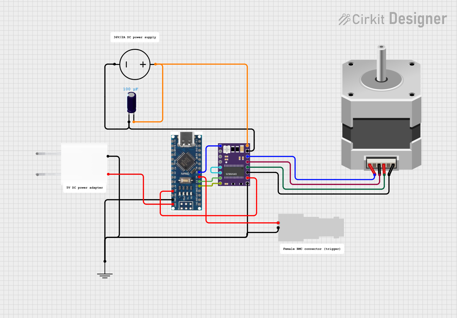
Connecting the Stepper Driver to a Circuit

  1. Connect the motor windings to the appropriate pins on the driver.
  2. Apply the logic supply voltage (VDD) and ground (GND) to the driver.
  3. Connect the motor supply voltage (VMOT) to the driver, ensuring it matches the motor's requirements.
  4. Set the desired microstepping resolution using the MS1, MS2, and MS3 pins.
  5. Connect the STEP and DIR pins to the output pins of your microcontroller.

Important Considerations and Best Practices

  • Always ensure that the power supply voltage and current ratings match the requirements of both the stepper motor and the driver.
  • Use decoupling capacitors close to the driver's power supply pins to minimize voltage spikes.
  • Avoid disconnecting the motor while the driver is powered to prevent damage.
  • Configure microstepping according to the precision and smoothness required for your application.
  • Use heat sinks or cooling systems if the driver operates at high currents for extended periods.

Example Code for Arduino UNO

// Define the stepper motor connections and Arduino digital pins
#define DIR_PIN 2
#define STEP_PIN 3
#define ENABLE_PIN 4

void setup() {
  // Set the pin modes for the stepper driver
  pinMode(DIR_PIN, OUTPUT);
  pinMode(STEP_PIN, OUTPUT);
  pinMode(ENABLE_PIN, OUTPUT);

  // Enable the stepper driver
  digitalWrite(ENABLE_PIN, LOW);
}

void loop() {
  // Set the direction of the stepper motor
  digitalWrite(DIR_PIN, HIGH); // Set to LOW to change direction

  // Move the stepper motor one step
  digitalWrite(STEP_PIN, HIGH);
  delayMicroseconds(1000); // Delay determines the speed
  digitalWrite(STEP_PIN, LOW);
  delayMicroseconds(1000);
}

Troubleshooting and FAQs

Common Issues

  • Motor does not move: Check power supply, wiring, and ensure the enable pin is set correctly.
  • Motor stutters or misses steps: Verify that the current limit is set properly, and the power supply is adequate.
  • Motor overheats: Reduce current, check for proper microstepping settings, or improve cooling.

Solutions and Tips

  • Ensure all connections are secure and free from shorts.
  • Use a multimeter to verify the voltage at the motor and logic supply pins.
  • If using microstepping, ensure that the MS pins are set to the correct logic levels.

FAQs

Q: Can I use a stepper driver with any stepper motor? A: While stepper drivers are generally compatible with a wide range of stepper motors, always check the motor's voltage and current requirements to ensure compatibility with the driver's specifications.

Q: How do I set the current limit on my stepper driver? A: The current limit is typically set via a potentiometer on the driver board or through digital configuration, depending on the model. Refer to the specific driver's datasheet for instructions.

Q: What is microstepping and why would I use it? A: Microstepping divides a full step into smaller steps, allowing for smoother and more precise motor movements. It is used when high-resolution positioning is required.