Cirkit Designer Logo
Cirkit Designer
Your all-in-one circuit design IDE
Home / 
Component Documentation

How to Use Adafruit ADS122C04 24-Bit ADC - 4 Channel 2-kSPS - STEMMA QT / Qwiic: Examples, Pinouts, and Specs

Image of Adafruit ADS122C04 24-Bit ADC - 4 Channel 2-kSPS - STEMMA QT / Qwiic
Cirkit Designer LogoDesign with Adafruit ADS122C04 24-Bit ADC - 4 Channel 2-kSPS - STEMMA QT / Qwiic in Cirkit Designer

Introduction

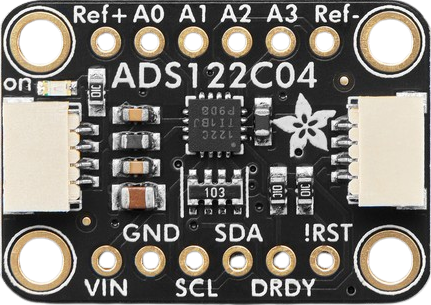
The Adafruit ADS122C04 (Part ID: 6432) is a high-resolution analog-to-digital converter (ADC) designed for precision measurement applications. With 24-bit resolution and a sampling rate of up to 2,000 samples per second (2 kSPS), this ADC is ideal for applications requiring accurate and reliable analog signal conversion. It features four input channels, making it suitable for multi-sensor setups, and is equipped with STEMMA QT / Qwiic connectors for seamless integration into I2C-based systems.

Explore Projects Built with Adafruit ADS122C04 24-Bit ADC - 4 Channel 2-kSPS - STEMMA QT / Qwiic

Use Cirkit Designer to design, explore, and prototype these projects online. Some projects support real-time simulation. Click "Open Project" to start designing instantly!
Raspberry Pi 4B-Based Current Monitoring System with I2C OLED Display
Image of Virtual Energy Monitoring Circuit: A project utilizing Adafruit ADS122C04 24-Bit ADC - 4 Channel 2-kSPS - STEMMA QT / Qwiic in a practical application
This circuit features a Raspberry Pi 4B as the central processing unit, interfaced with an Adafruit ADS1115 16-bit I2C ADC for analog-to-digital conversion and a 0.96" OLED display for visual output. The ADS1115 is connected to a current sensor for measuring electrical current, with the sensor's output and burden pins connected to the ADC's analog input channels. The Raspberry Pi communicates with both the ADC and the OLED display over the I2C bus, using its GPIO2 and GPIO3 pins for data (SDA) and clock (SCL) lines, respectively.
Cirkit Designer LogoOpen Project in Cirkit Designer
Raspberry Pi 4B with I2C Sensor Data Acquisition and OLED Display
Image of Task02: A project utilizing Adafruit ADS122C04 24-Bit ADC - 4 Channel 2-kSPS - STEMMA QT / Qwiic in a practical application
This circuit features a Raspberry Pi 4B as the central processing unit, interfaced with an Adafruit ADS1115 16-bit ADC for analog-to-digital conversion, a current sensor, and a ZMPT101B voltage sensor for electrical parameter measurement. The Raspberry Pi communicates with the ADC and a 0.96" OLED display via I2C (using GPIO2 and GPIO3 for SDA and SCL lines, respectively), allowing for the monitoring and display of current and voltage readings. The ADC is connected to the current sensor and voltage sensor to digitize the analog signals for processing by the Raspberry Pi.
Cirkit Designer LogoOpen Project in Cirkit Designer
Raspberry Pi 4B with I2C Current Sensing and OLED Display
Image of iot task 2: A project utilizing Adafruit ADS122C04 24-Bit ADC - 4 Channel 2-kSPS - STEMMA QT / Qwiic in a practical application
This circuit features a Raspberry Pi 4B as the central processing unit, interfaced with an Adafruit ADS1115 16-bit I2C ADC for analog-to-digital conversion and a 0.96" OLED display for visual output. The ADC is connected to a current sensor for measuring electrical current, with the sensor's output connected to the ADC's AIN0 pin and the burden resistor connected to AIN1. The Raspberry Pi communicates with both the ADC and the OLED display over the I2C bus, using GPIO2 (SDA) and GPIO3 (SCL) for data exchange.
Cirkit Designer LogoOpen Project in Cirkit Designer
Arduino UNO WiFi Sensor Data Acquisition and Display System
Image of Senior Design: A project utilizing Adafruit ADS122C04 24-Bit ADC - 4 Channel 2-kSPS - STEMMA QT / Qwiic in a practical application
This circuit features an Arduino UNO R4 WiFi microcontroller interfacing with a 4-channel ADC to read from various sensors and display data on an I2C LCD screen. A pushbutton provides user input, and a DC-DC buck converter regulates the power supply from a 12V source.
Cirkit Designer LogoOpen Project in Cirkit Designer

Explore Projects Built with Adafruit ADS122C04 24-Bit ADC - 4 Channel 2-kSPS - STEMMA QT / Qwiic

Use Cirkit Designer to design, explore, and prototype these projects online. Some projects support real-time simulation. Click "Open Project" to start designing instantly!
Image of Virtual Energy Monitoring Circuit: A project utilizing Adafruit ADS122C04 24-Bit ADC - 4 Channel 2-kSPS - STEMMA QT / Qwiic in a practical application
Raspberry Pi 4B-Based Current Monitoring System with I2C OLED Display
This circuit features a Raspberry Pi 4B as the central processing unit, interfaced with an Adafruit ADS1115 16-bit I2C ADC for analog-to-digital conversion and a 0.96" OLED display for visual output. The ADS1115 is connected to a current sensor for measuring electrical current, with the sensor's output and burden pins connected to the ADC's analog input channels. The Raspberry Pi communicates with both the ADC and the OLED display over the I2C bus, using its GPIO2 and GPIO3 pins for data (SDA) and clock (SCL) lines, respectively.
Cirkit Designer LogoOpen Project in Cirkit Designer
Image of Task02: A project utilizing Adafruit ADS122C04 24-Bit ADC - 4 Channel 2-kSPS - STEMMA QT / Qwiic in a practical application
Raspberry Pi 4B with I2C Sensor Data Acquisition and OLED Display
This circuit features a Raspberry Pi 4B as the central processing unit, interfaced with an Adafruit ADS1115 16-bit ADC for analog-to-digital conversion, a current sensor, and a ZMPT101B voltage sensor for electrical parameter measurement. The Raspberry Pi communicates with the ADC and a 0.96" OLED display via I2C (using GPIO2 and GPIO3 for SDA and SCL lines, respectively), allowing for the monitoring and display of current and voltage readings. The ADC is connected to the current sensor and voltage sensor to digitize the analog signals for processing by the Raspberry Pi.
Cirkit Designer LogoOpen Project in Cirkit Designer
Image of iot task 2: A project utilizing Adafruit ADS122C04 24-Bit ADC - 4 Channel 2-kSPS - STEMMA QT / Qwiic in a practical application
Raspberry Pi 4B with I2C Current Sensing and OLED Display
This circuit features a Raspberry Pi 4B as the central processing unit, interfaced with an Adafruit ADS1115 16-bit I2C ADC for analog-to-digital conversion and a 0.96" OLED display for visual output. The ADC is connected to a current sensor for measuring electrical current, with the sensor's output connected to the ADC's AIN0 pin and the burden resistor connected to AIN1. The Raspberry Pi communicates with both the ADC and the OLED display over the I2C bus, using GPIO2 (SDA) and GPIO3 (SCL) for data exchange.
Cirkit Designer LogoOpen Project in Cirkit Designer
Image of Senior Design: A project utilizing Adafruit ADS122C04 24-Bit ADC - 4 Channel 2-kSPS - STEMMA QT / Qwiic in a practical application
Arduino UNO WiFi Sensor Data Acquisition and Display System
This circuit features an Arduino UNO R4 WiFi microcontroller interfacing with a 4-channel ADC to read from various sensors and display data on an I2C LCD screen. A pushbutton provides user input, and a DC-DC buck converter regulates the power supply from a 12V source.
Cirkit Designer LogoOpen Project in Cirkit Designer

Common Applications

  • Precision sensor measurements (e.g., temperature, pressure, or strain gauges)
  • Data acquisition systems
  • Industrial automation and control
  • Scientific instrumentation
  • IoT devices requiring high-resolution analog data

Technical Specifications

The following table outlines the key technical specifications of the Adafruit ADS122C04:

Parameter Value
Resolution 24-bit
Sampling Rate Up to 2,000 samples per second
Input Channels 4
Input Voltage Range 0 to 5V (single-ended)
Interface I2C
Operating Voltage 3.3V or 5V
Current Consumption ~1.5 mA (typical)
Operating Temperature Range -40°C to +125°C
Dimensions 25mm x 17mm x 4mm

Pin Configuration and Descriptions

The Adafruit ADS122C04 features the following pinout:

Pin Name Type Description
VIN Power Input Power supply input (3.3V or 5V).
GND Ground Ground connection.
SDA I2C Data Serial data line for I2C communication.
SCL I2C Clock Serial clock line for I2C communication.
AIN0 Analog Input Analog input channel 0.
AIN1 Analog Input Analog input channel 1.
AIN2 Analog Input Analog input channel 2.
AIN3 Analog Input Analog input channel 3.
STEMMA QT I2C Connector STEMMA QT / Qwiic connector for plug-and-play I2C integration.

Usage Instructions

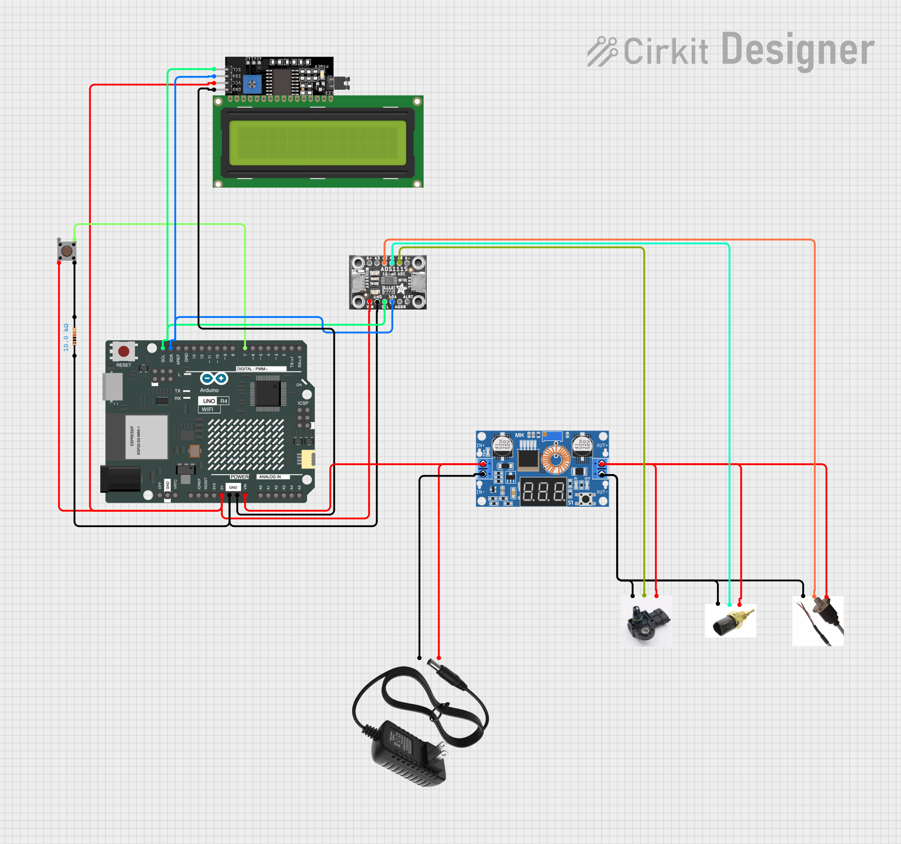
How to Use the Component in a Circuit

  1. Power the ADC: Connect the VIN pin to a 3.3V or 5V power source and the GND pin to ground.
  2. Connect to I2C: Use the SDA and SCL pins to connect the ADC to your microcontroller's I2C bus. Alternatively, use the STEMMA QT / Qwiic connector for a plug-and-play setup.
  3. Connect Analog Inputs: Attach your analog sensors or signals to the AIN0–AIN3 pins. Ensure the input voltage does not exceed the ADC's input range (0–5V).
  4. Configure the ADC: Use the I2C interface to configure the ADC settings, such as sampling rate, gain, and input channel selection.

Important Considerations and Best Practices

  • Input Voltage Range: Ensure that the input signals are within the ADC's specified range (0–5V). Use a voltage divider or level shifter if necessary.
  • Noise Reduction: Minimize noise by using short, shielded cables for analog inputs and placing decoupling capacitors near the ADC.
  • I2C Pull-Up Resistors: If your system does not already include pull-up resistors on the I2C lines, add 4.7kΩ resistors to SDA and SCL.
  • Power Supply Stability: Use a stable and clean power supply to avoid introducing noise into the ADC measurements.

Example Code for Arduino UNO

Below is an example of how to use the Adafruit ADS122C04 with an Arduino UNO:

#include <Wire.h>
#include <Adafruit_ADS1X15.h>

// Create an instance of the ADS122C04 ADC
Adafruit_ADS1115 ads; // Note: ADS1115 library is compatible with ADS122C04

void setup() {
  Serial.begin(9600);
  while (!Serial); // Wait for Serial Monitor to open

  // Initialize I2C communication
  if (!ads.begin()) {
    Serial.println("Failed to initialize ADS122C04. Check connections!");
    while (1);
  }
  Serial.println("ADS122C04 initialized successfully!");

  // Set gain to 1 (default) for full-scale input range of ±4.096V
  ads.setGain(GAIN_ONE);
}

void loop() {
  // Read analog value from channel 0
  int16_t adcValue = ads.readADC_SingleEnded(0);

  // Convert ADC value to voltage
  float voltage = adcValue * 0.125; // 0.125mV per bit for GAIN_ONE

  // Print the voltage to Serial Monitor
  Serial.print("Channel 0 Voltage: ");
  Serial.print(voltage);
  Serial.println(" mV");

  delay(1000); // Wait 1 second before next reading
}

Troubleshooting and FAQs

Common Issues

  1. ADC Not Detected on I2C Bus

    • Cause: Incorrect wiring or missing pull-up resistors on SDA/SCL lines.
    • Solution: Verify connections and ensure 4.7kΩ pull-up resistors are present.
  2. Inaccurate Readings

    • Cause: Noise or input signals exceeding the ADC's range.
    • Solution: Use shielded cables, decoupling capacitors, and ensure input signals are within 0–5V.
  3. No Output on Serial Monitor

    • Cause: Incorrect baud rate or failed ADC initialization.
    • Solution: Check the Serial Monitor baud rate (set to 9600) and verify the ADC is properly powered and connected.

FAQs

Q: Can I use this ADC with a 3.3V microcontroller?
A: Yes, the ADS122C04 is compatible with both 3.3V and 5V systems.

Q: What is the maximum sampling rate?
A: The ADC supports a maximum sampling rate of 2,000 samples per second (2 kSPS).

Q: Can I use all four channels simultaneously?
A: The ADC can measure one channel at a time. You can switch between channels programmatically using the I2C interface.

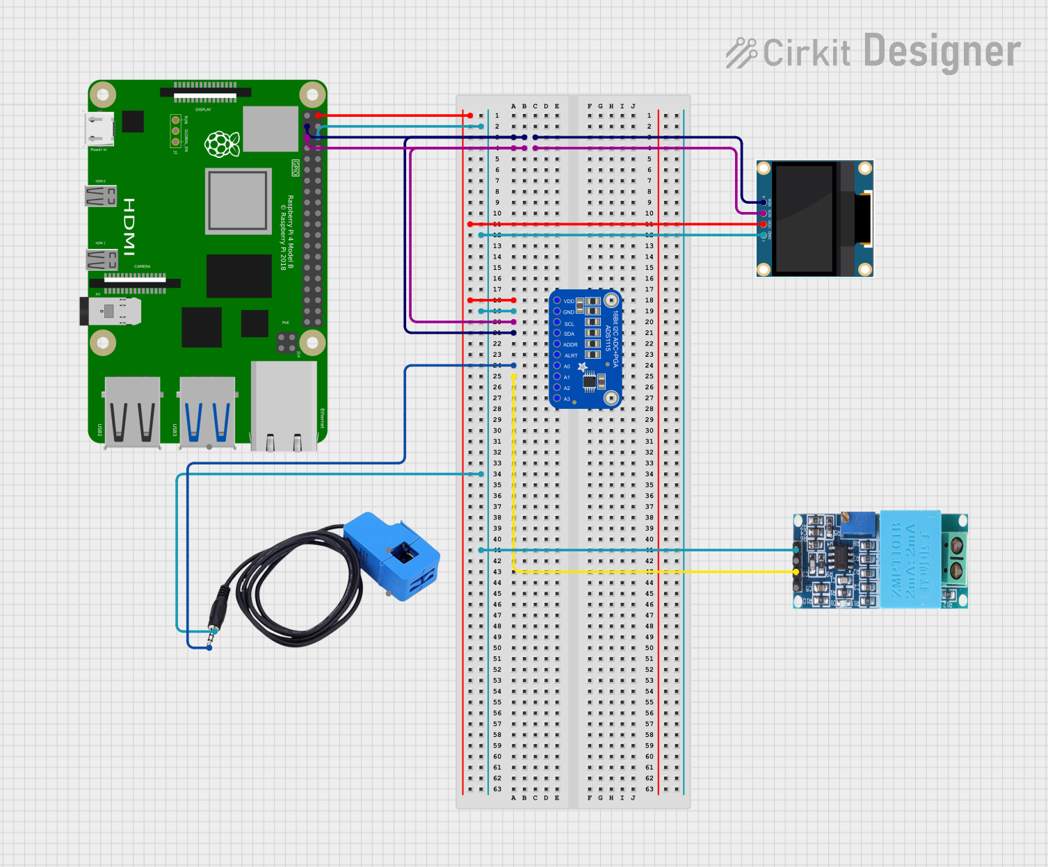
Q: Is the ADS122C04 compatible with Raspberry Pi?
A: Yes, the ADC can be used with Raspberry Pi via the I2C interface. Use the STEMMA QT / Qwiic connector for easy integration.

Q: Do I need an external clock for the ADC?
A: No, the ADS122C04 has an internal oscillator and does not require an external clock.