How to Use 12V Relay with JD-VCC: Examples, Pinouts, and Specs
Introduction
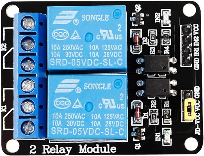
The 12V Relay with JD-VCC is an electromechanical switch designed to control high-power devices using low-power control signals. It operates at 12 volts and features a JD-VCC pin, which allows for the separation of the control circuit from the load circuit. This design ensures safe and efficient switching, making it ideal for applications where electrical isolation is critical.
Explore Projects Built with 12V Relay with JD-VCC


Explore Projects Built with 12V Relay with JD-VCC
Common Applications and Use Cases
- Home automation systems (e.g., controlling lights, fans, or appliances)
- Industrial control systems
- Motor control circuits
- IoT projects requiring high-power device control
- Automotive electronics
Technical Specifications
Key Technical Details
- Operating Voltage (Coil): 12V DC
- Trigger Voltage (Control Signal): 3.3V to 5V (logic level compatible)
- Maximum Switching Voltage (Load): 250V AC or 30V DC
- Maximum Switching Current (Load): 10A
- Isolation: Optocoupler isolation between control and load circuits
- JD-VCC Pin: Provides separate power for the relay coil
- Relay Type: SPDT (Single Pole Double Throw)
Pin Configuration and Descriptions
The 12V Relay module typically has the following pins:
| Pin Name | Description |
|---|---|
| VCC | Connect to the 5V power supply for the control circuit. |
| GND | Ground connection for the control circuit. |
| IN | Control signal input (logic HIGH activates the relay). |
| JD-VCC | Connect to a 12V power supply to power the relay coil. |
| COM | Common terminal for the load circuit. |
| NO | Normally Open terminal (connected to COM when the relay is activated). |
| NC | Normally Closed terminal (connected to COM when the relay is not activated). |
Note: The JD-VCC pin is used to power the relay coil separately from the control circuit. This ensures electrical isolation and prevents interference.
Usage Instructions
How to Use the Component in a Circuit
Power the Relay Module:
- Connect the VCC pin to a 5V power supply and the GND pin to ground.
- Connect the JD-VCC pin to a 12V power supply to energize the relay coil.
Control the Relay:
- Connect the IN pin to a digital output pin of a microcontroller (e.g., Arduino).
- Send a HIGH signal (3.3V or 5V) to the IN pin to activate the relay.
Connect the Load:
- Connect the load circuit to the COM, NO, and/or NC terminals based on your requirements:
- Use the NO terminal if you want the load to be powered only when the relay is activated.
- Use the NC terminal if you want the load to be powered when the relay is not activated.
- Connect the load circuit to the COM, NO, and/or NC terminals based on your requirements:
Ensure Proper Isolation:
- Use the JD-VCC jumper to separate the control and load circuits if needed. Remove the jumper and provide a separate 12V supply to JD-VCC for complete isolation.
Important Considerations and Best Practices
- Always check the voltage and current ratings of the relay before connecting a load.
- Use a flyback diode across the relay coil to protect the circuit from voltage spikes.
- Ensure proper grounding to avoid noise or interference in the control circuit.
- Avoid exceeding the maximum switching voltage and current to prevent damage to the relay.
- If using with an Arduino UNO, ensure the control pin is configured as an output.
Example Arduino Code
// Example code to control a 12V Relay with JD-VCC using an Arduino UNO

const int relayPin = 7; // Define the digital pin connected to the relay IN pin

void setup() {
  pinMode(relayPin, OUTPUT); // Set the relay pin as an output
  digitalWrite(relayPin, LOW); // Ensure the relay is off at startup
}

void loop() {
  digitalWrite(relayPin, HIGH); // Activate the relay
  delay(1000); // Keep the relay on for 1 second
  digitalWrite(relayPin, LOW); // Deactivate the relay
  delay(1000); // Keep the relay off for 1 second
}
Note: Ensure the Arduino is powered properly, and the relay module is connected securely.
Troubleshooting and FAQs
Common Issues and Solutions
Relay Not Activating:
- Cause: Insufficient voltage or current to the JD-VCC pin.
- Solution: Verify that the JD-VCC pin is connected to a stable 12V power supply.
Control Signal Not Working:
- Cause: Incorrect connection or insufficient voltage at the IN pin.
- Solution: Ensure the IN pin is connected to a digital output pin of the microcontroller and receiving a HIGH signal.
Load Not Switching:
- Cause: Incorrect wiring of the load circuit.
- Solution: Double-check the connections to the COM, NO, and NC terminals.
Interference in Control Circuit:
- Cause: Lack of isolation between control and load circuits.
- Solution: Remove the JD-VCC jumper and provide a separate 12V supply to JD-VCC.
FAQs
Q: Can I use the relay with a 3.3V microcontroller like the ESP32?
A: Yes, the relay can be triggered with a 3.3V control signal. Ensure the IN pin receives a HIGH signal of at least 3.3V.
Q: What is the purpose of the JD-VCC pin?
A: The JD-VCC pin allows the relay coil to be powered separately from the control circuit, providing electrical isolation and reducing interference.
Q: Can the relay switch both AC and DC loads?
A: Yes, the relay can switch AC loads up to 250V and DC loads up to 30V, as long as the current does not exceed 10A.
Q: Do I need a flyback diode for this relay module?
A: Most relay modules with JD-VCC include a built-in flyback diode. However, verify the module's design or add an external diode if necessary.