
How to Use max98357a amplifier: Examples, Pinouts, and Specs
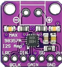
 Design with max98357a amplifier in Cirkit Designer
Introduction
The MAX98357A is a digital audio amplifier designed to deliver high-quality sound amplification with minimal power consumption. It integrates a digital-to-analog converter (DAC) and supports I2S (Inter-IC Sound) audio input, making it a versatile choice for audio applications. Its compact design and efficient performance make it ideal for portable devices, smart speakers, IoT audio systems, and other audio-related projects.
Explore Projects Built with max98357a amplifier
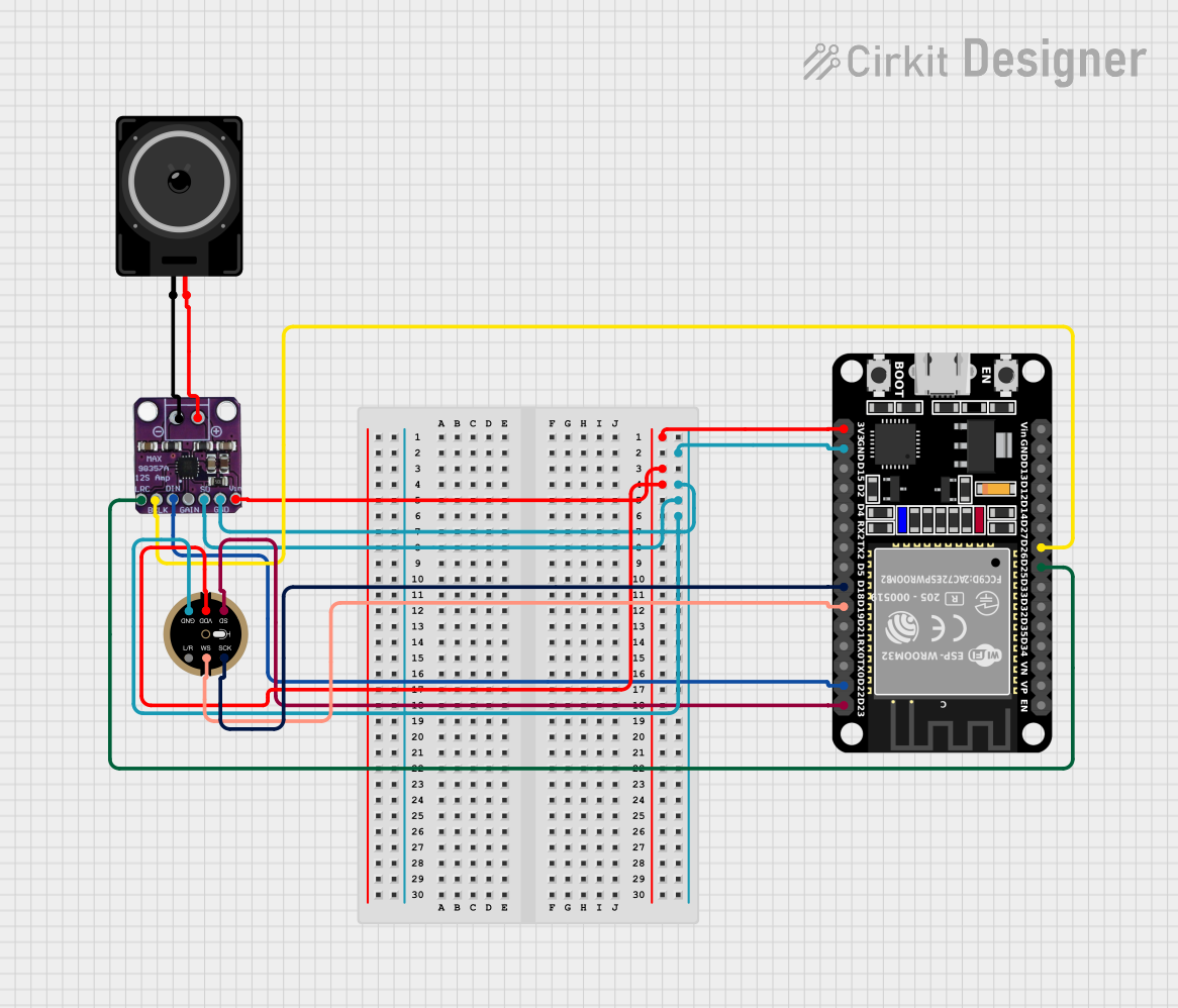 Open Project in Cirkit Designer
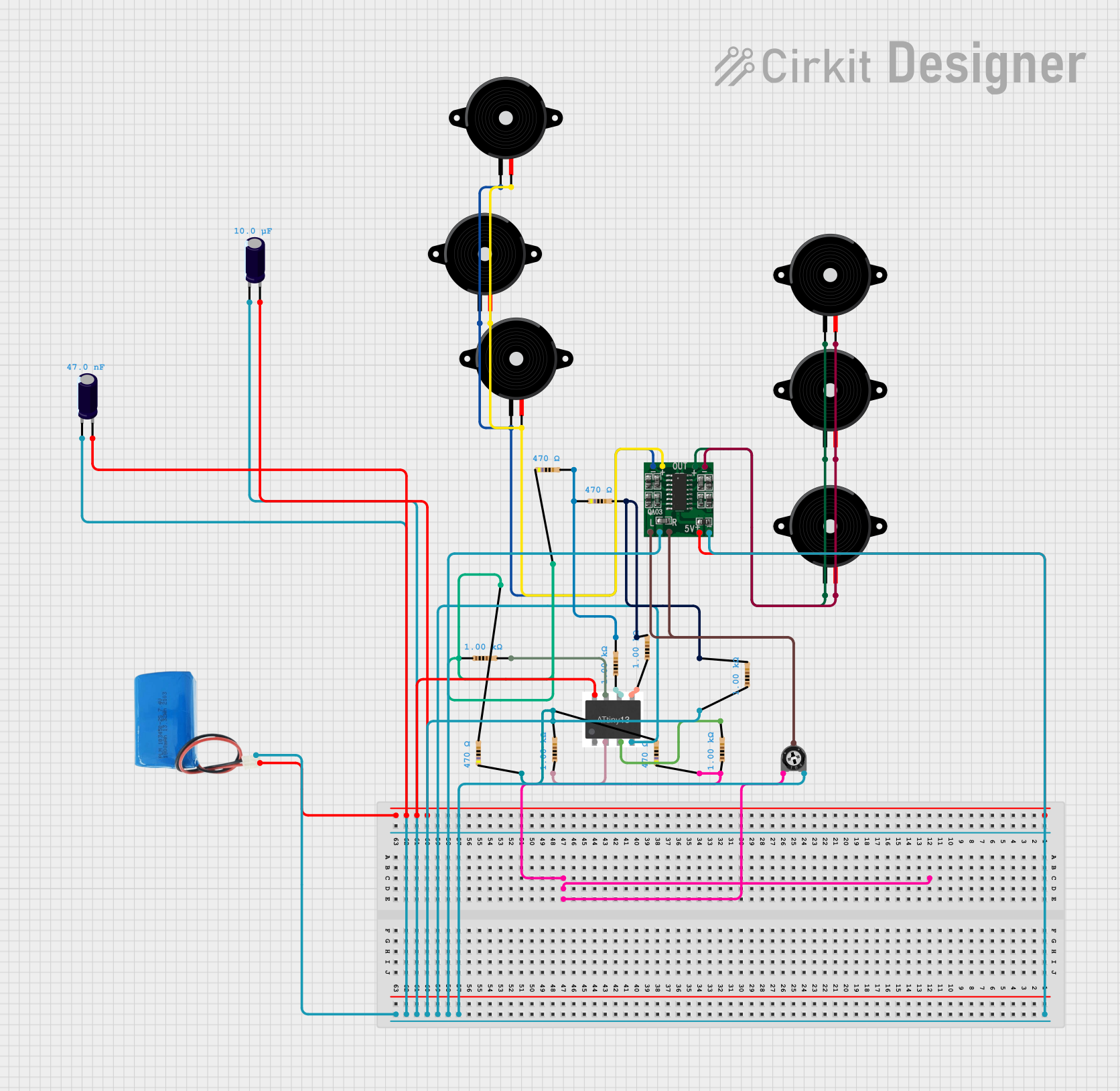 Open Project in Cirkit Designer
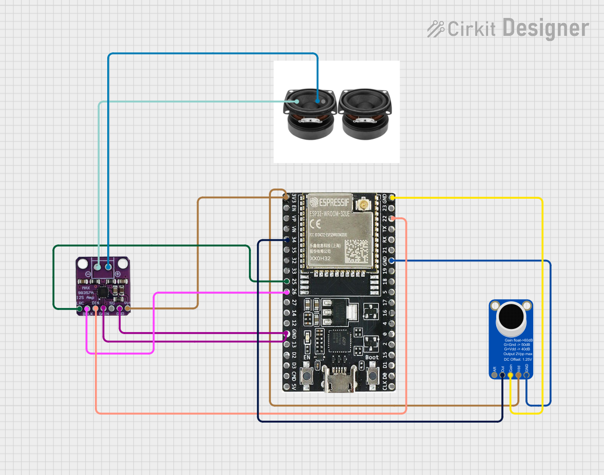 Open Project in Cirkit Designer
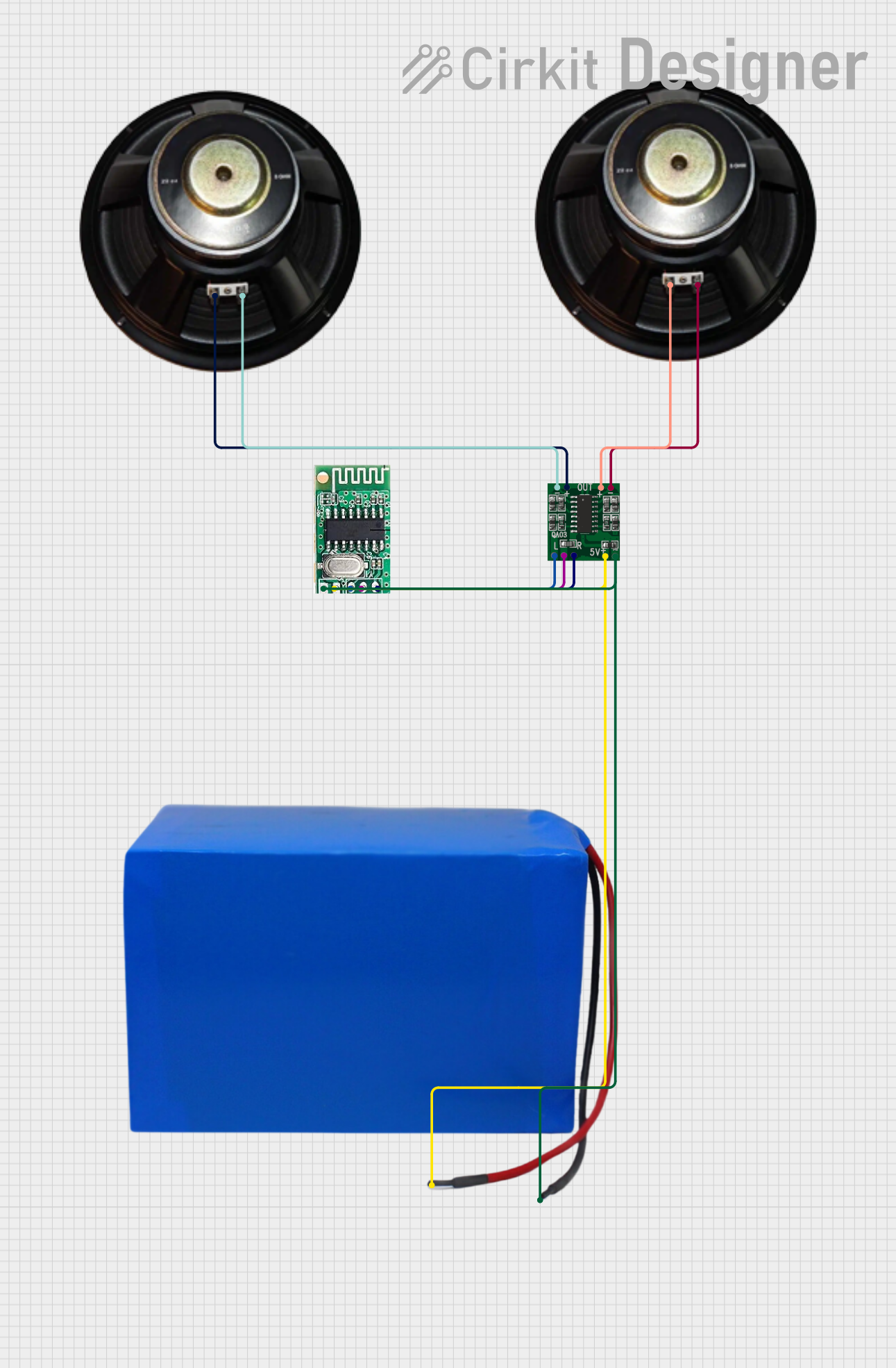 Open Project in Cirkit Designer
Explore Projects Built with max98357a amplifier
Open Project in Cirkit DesignerOpen Project in Cirkit DesignerOpen Project in Cirkit DesignerOpen Project in Cirkit DesignerCommon Applications
- Portable audio devices
- Smart home audio systems
- IoT devices with audio output
- Embedded systems requiring sound amplification
- DIY audio projects
Technical Specifications
Key Technical Details
| Parameter | Value |
|---|---|
| Supply Voltage (VDD) | 2.5V to 5.5V |
| Output Power | 3.2W at 4Ω load, 10% THD+N, VDD = 5V |
| Input Format | I2S digital audio |
| Sampling Rates | 8kHz to 96kHz |
| Efficiency | Up to 92% |
| Shutdown Current | 0.2µA (typical) |
| Output Load | 4Ω or 8Ω |
| Operating Temperature | -40°C to +85°C |
Pin Configuration and Descriptions
The MAX98357A is available in a 9-pin WLP (Wafer-Level Package) or 8-pin TDFN package. Below is the pin configuration for the 8-pin TDFN package:
| Pin Number | Pin Name | Description |
|---|---|---|
| 1 | GND | Ground connection |
| 2 | BCLK | Bit clock input for I2S |
| 3 | LRCLK | Left/Right clock input for I2S |
| 4 | DIN | Data input for I2S |
| 5 | SCL/SCLKO | Mode selection or clock output (optional) |
| 6 | VDD | Power supply input |
| 7 | OUT+ | Positive speaker output |
| 8 | OUT- | Negative speaker output |
Usage Instructions
How to Use the MAX98357A in a Circuit
- Power Supply: Connect the VDD pin to a stable power source (2.5V to 5.5V). Ensure proper decoupling with a capacitor (e.g., 10µF) close to the VDD pin.
- Ground Connection: Connect the GND pin to the ground of your circuit.
- I2S Input:
- Connect the
BCLKpin to the bit clock signal from your microcontroller or audio source. - Connect the
LRCLKpin to the left/right clock signal. - Connect the
DINpin to the digital audio data signal.
- Connect the
- Speaker Connection: Connect a speaker (4Ω or 8Ω) to the
OUT+andOUT-pins. Use proper wiring to avoid short circuits. - Mode Selection: Configure the SCL/SCLKO pin for the desired mode (e.g., mono or stereo audio). Refer to the datasheet for specific configurations.
Important Considerations
- Speaker Impedance: Use a speaker with the recommended impedance (4Ω or 8Ω) to ensure optimal performance.
- Heat Dissipation: Although the MAX98357A is highly efficient, ensure proper ventilation or heat sinking if operating at high power levels.
- I2S Configuration: Ensure that the I2S settings (bit depth, sampling rate, etc.) on your microcontroller match the MAX98357A's supported formats.
Example: Connecting to an Arduino UNO
The MAX98357A can be easily interfaced with an Arduino UNO for audio playback. Below is an example of how to connect and program the MAX98357A with an Arduino:
Wiring Diagram
| MAX98357A Pin | Arduino Pin |
|---|---|
| BCLK | Pin 9 |
| LRCLK | Pin 10 |
| DIN | Pin 11 |
| GND | GND |
| VDD | 5V |
Arduino Code
#include <I2S.h> // Include the I2S library for audio communication

void setup() {
  // Initialize I2S for audio output
  if (!I2S.begin(I2S_PHILIPS_MODE, 44100)) {
    // Check if I2S initialization failed
    while (1) {
      // Stay in this loop if initialization fails
    }
  }
}

void loop() {
  // Example: Send a simple sine wave to the MAX98357A
  for (int i = 0; i < 360; i++) {
    // Generate a sine wave sample
    int sample = 32767 * sin(i * PI / 180);
    I2S.write(sample); // Send the sample to the amplifier
  }
}
Notes:
- The above code assumes the use of the Arduino I2S library. Ensure your Arduino board supports I2S communication.
- Adjust the sampling rate (e.g., 44100 Hz) and audio data as needed for your application.
Troubleshooting and FAQs
Common Issues and Solutions
No Sound Output:
- Verify all connections, especially the I2S signals (BCLK, LRCLK, DIN).
- Ensure the speaker is properly connected to the
OUT+andOUT-pins. - Check the power supply voltage (2.5V to 5.5V) and ensure it is stable.
Distorted Audio:
- Ensure the I2S settings (bit depth, sampling rate) match the audio source.
- Check for loose or poor-quality connections to the speaker.
Overheating:
- Verify that the speaker impedance is within the recommended range (4Ω or 8Ω).
- Reduce the output power if operating at high levels for extended periods.
I2S Communication Issues:
- Confirm that the microcontroller supports I2S and is configured correctly.
- Double-check the wiring of the BCLK, LRCLK, and DIN pins.
FAQs
Q: Can I use the MAX98357A with a 3.3V microcontroller?
A: Yes, the MAX98357A supports a supply voltage range of 2.5V to 5.5V, making it compatible with 3.3V systems.
Q: What type of speaker should I use?
A: Use a 4Ω or 8Ω speaker for optimal performance. Ensure the speaker can handle the output power of the amplifier.
Q: Does the MAX98357A support stereo audio?
A: The MAX98357A is a mono amplifier. For stereo applications, you can use two MAX98357A modules, one for each channel.
Q: Can I use the MAX98357A without a microcontroller?
A: No, the MAX98357A requires an I2S audio source, which is typically provided by a microcontroller or dedicated audio processor.