How to Use logic_level_converter: Examples, Pinouts, and Specs
Introduction
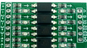
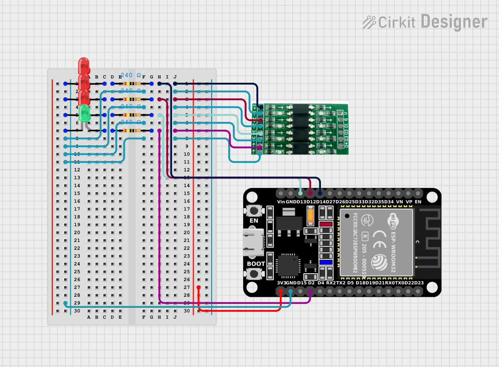
A Logic Level Converter is an essential device used to safely step up or step down voltage levels between different parts of a circuit. This allows components with different voltage requirements to communicate effectively. For instance, it enables a 3.3V microcontroller to interface with a 5V sensor or vice versa. This component is widely used in various applications, including microcontroller projects, sensor interfacing, and communication between different voltage domains.
Explore Projects Built with logic_level_converter


Explore Projects Built with logic_level_converter
Technical Specifications
Key Technical Details
- Voltage Range: 1.8V to 5V
- Current Rating: Typically up to 50mA per channel
- Channels: 4 bi-directional channels
- Power Consumption: Minimal, typically in the microampere range
- Operating Temperature: -40°C to 85°C
Pin Configuration and Descriptions
| Pin | Name | Description |
|---|---|---|
| 1 | HV | High Voltage (e.g., 5V) |
| 2 | LV | Low Voltage (e.g., 3.3V) |
| 3 | GND | Ground |
| 4 | TXI1 | High Voltage Input Channel 1 |
| 5 | TXO1 | Low Voltage Output Channel 1 |
| 6 | TXI2 | High Voltage Input Channel 2 |
| 7 | TXO2 | Low Voltage Output Channel 2 |
| 8 | TXI3 | High Voltage Input Channel 3 |
| 9 | TXO3 | Low Voltage Output Channel 3 |
| 10 | TXI4 | High Voltage Input Channel 4 |
| 11 | TXO4 | Low Voltage Output Channel 4 |
Usage Instructions
How to Use the Component in a Circuit
Power Connections:
- Connect the HV pin to the higher voltage supply (e.g., 5V).
- Connect the LV pin to the lower voltage supply (e.g., 3.3V).
- Connect the GND pin to the common ground of the circuit.
Signal Connections:
- Connect the high voltage signal to the corresponding TXI pin.
- Connect the low voltage signal to the corresponding TXO pin.
Important Considerations and Best Practices
- Voltage Compatibility: Ensure that the HV and LV voltages are within the specified range of the logic level converter.
- Current Limitation: Do not exceed the current rating of the converter to avoid damage.
- Proper Grounding: Ensure a common ground between the high and low voltage sides to prevent floating voltages.
- Noise Reduction: Use decoupling capacitors close to the power pins to reduce noise and improve stability.
Example: Connecting to an Arduino UNO
To interface a 3.3V sensor with a 5V Arduino UNO, follow these steps:
- Connect the HV pin to the 5V pin on the Arduino.
- Connect the LV pin to the 3.3V pin on the Arduino.
- Connect the GND pin to the GND pin on the Arduino.
- Connect the sensor's data pin to the TXO1 pin.
- Connect the TXI1 pin to the corresponding digital input pin on the Arduino.
Sample Arduino Code
// Example code to read data from a 3.3V sensor using a 5V Arduino UNO

const int sensorPin = 2; // Pin connected to TXI1 of the logic level converter

void setup() {
  Serial.begin(9600); // Initialize serial communication
  pinMode(sensorPin, INPUT); // Set sensor pin as input
}

void loop() {
  int sensorValue = digitalRead(sensorPin); // Read sensor value
  Serial.println(sensorValue); // Print sensor value to serial monitor
  delay(1000); // Wait for 1 second
}
Troubleshooting and FAQs
Common Issues Users Might Face
No Signal Conversion:
- Solution: Check the power connections (HV, LV, and GND) and ensure they are correctly connected.
Incorrect Voltage Levels:
- Solution: Verify that the HV and LV voltages are within the specified range and that the ground is common.
Intermittent Signal:
- Solution: Use decoupling capacitors close to the power pins to reduce noise.
FAQs
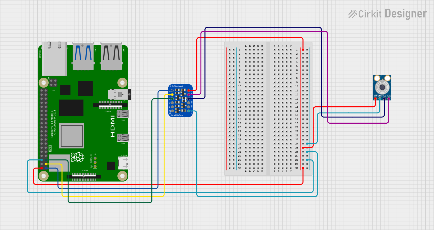
Q1: Can I use the logic level converter for I2C communication?
- A1: Yes, the logic level converter can be used for I2C communication. Connect the SDA and SCL lines through the converter channels.
Q2: What is the maximum data rate supported by the logic level converter?
- A2: The maximum data rate depends on the specific model, but typically it can handle up to 400kHz for I2C communication.
Q3: Can I use the logic level converter for analog signals?
- A3: No, the logic level converter is designed for digital signals only. For analog signals, use an appropriate analog level shifter.
By following this documentation, users can effectively utilize the logic level converter in their projects, ensuring safe and reliable communication between components with different voltage requirements.