How to Use ESP32-WROOM-32: Examples, Pinouts, and Specs
Introduction
The ESP32-WROOM-32 is a powerful Wi-Fi and Bluetooth microcontroller module manufactured by Generic. It features dual-core processing capabilities, making it an excellent choice for Internet of Things (IoT) applications, embedded systems, and wireless communication projects. With its robust performance and versatile connectivity options, the ESP32-WROOM-32 is widely used in smart home devices, industrial automation, wearable electronics, and more.
Explore Projects Built with ESP32-WROOM-32


Explore Projects Built with ESP32-WROOM-32
Common Applications
- IoT devices and smart home automation
- Wireless sensor networks
- Wearable electronics
- Industrial control systems
- Robotics and drones
- Audio streaming and Bluetooth applications
Technical Specifications
The ESP32-WROOM-32 module is built around the ESP32-D0WDQ6 chip and offers a rich set of features for developers. Below are the key technical specifications:
General Specifications
| Parameter | Value |
|---|---|
| Manufacturer | Generic |
| Part ID | ESP32-WROOM-32 |
| Microcontroller | ESP32-D0WDQ6 |
| Core Architecture | Dual-core Xtensa® 32-bit LX6 |
| Clock Speed | Up to 240 MHz |
| Flash Memory | 4 MB (default) |
| SRAM | 520 KB |
| Wireless Connectivity | Wi-Fi 802.11 b/g/n, Bluetooth v4.2 BR/EDR and BLE |
| Operating Voltage | 3.0V to 3.6V |
| Operating Temperature | -40°C to +85°C |
| Dimensions | 18 mm x 25.5 mm |
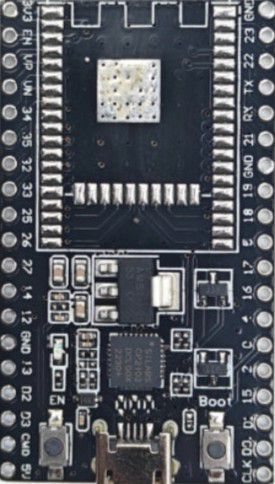
Pin Configuration
The ESP32-WROOM-32 module has 38 pins. Below is a summary of the pin configuration:
| Pin Number | Pin Name | Description |
|---|---|---|
| 1 | EN | Enable pin (active high) |
| 2 | IO0 | GPIO0, used for boot mode selection |
| 3 | IO1 (TX0) | GPIO1, UART0 TX |
| 4 | IO3 (RX0) | GPIO3, UART0 RX |
| 5 | IO4 | GPIO4, general-purpose I/O |
| 6 | IO5 | GPIO5, general-purpose I/O |
| 7 | IO12 | GPIO12, general-purpose I/O |
| 8 | IO13 | GPIO13, general-purpose I/O |
| 9 | IO14 | GPIO14, general-purpose I/O |
| 10 | IO15 | GPIO15, general-purpose I/O |
| ... | ... | ... (Refer to the datasheet for full pinout) |
Electrical Characteristics
| Parameter | Min Value | Max Value | Unit |
|---|---|---|---|
| Input Voltage (VDD) | 3.0 | 3.6 | V |
| Digital I/O Voltage | 0 | 3.3 | V |
| Wi-Fi Transmit Current | - | 240 | mA |
| Deep Sleep Current | - | 10 | µA |
Usage Instructions
The ESP32-WROOM-32 is easy to integrate into a variety of projects. Below are the steps and best practices for using the module:
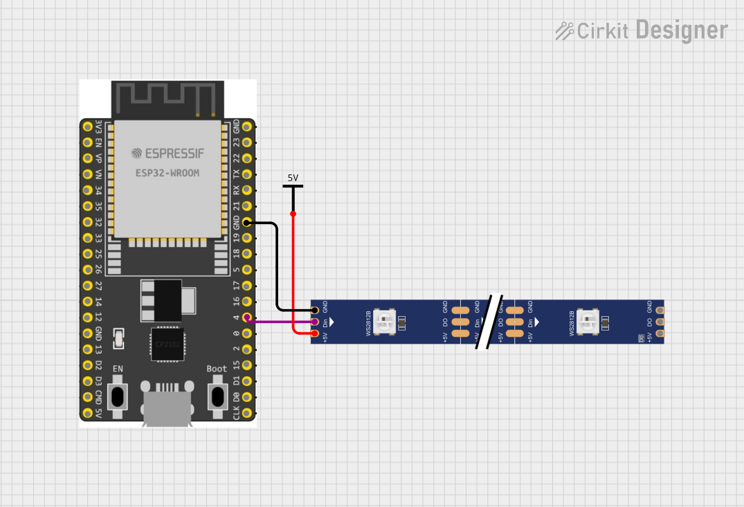
Basic Circuit Setup
- Power Supply: Provide a stable 3.3V power supply to the VDD pin. Avoid exceeding 3.6V to prevent damage.
- Boot Mode: Connect GPIO0 to GND during boot to enter flashing mode. For normal operation, leave GPIO0 unconnected or pull it high.
- UART Communication: Use the UART0 pins (TX0 and RX0) for programming and debugging. Connect these pins to a USB-to-serial converter for interfacing with a computer.
- External Components: Add decoupling capacitors (e.g., 10 µF and 0.1 µF) near the power pins to ensure stable operation.
Programming with Arduino IDE
The ESP32-WROOM-32 can be programmed using the Arduino IDE. Follow these steps:
- Install the ESP32 Board Manager in the Arduino IDE:
- Go to File > Preferences and add the following URL to the "Additional Board Manager URLs" field:
https://dl.espressif.com/dl/package_esp32_index.json - Open Tools > Board > Boards Manager, search for "ESP32," and install the package.
- Go to File > Preferences and add the following URL to the "Additional Board Manager URLs" field:
- Select the ESP32 Dev Module board from the Tools menu.
- Connect the ESP32-WROOM-32 to your computer via a USB-to-serial adapter.
- Write and upload your code.
Example Code: Blink an LED
// This example code blinks an LED connected to GPIO2 on the ESP32-WROOM-32.
// Ensure the LED's anode is connected to GPIO2 and the cathode to GND.

void setup() {
  pinMode(2, OUTPUT); // Set GPIO2 as an output pin
}

void loop() {
  digitalWrite(2, HIGH); // Turn the LED on
  delay(1000);           // Wait for 1 second
  digitalWrite(2, LOW);  // Turn the LED off
  delay(1000);           // Wait for 1 second
}
Best Practices
- Use level shifters when interfacing with 5V logic devices.
- Avoid powering the module directly from USB 5V without a voltage regulator.
- Use proper grounding to minimize noise and ensure stable operation.
Troubleshooting and FAQs
Common Issues
- Module Not Responding:
- Ensure the power supply is stable and within the 3.0V–3.6V range.
- Check the connections to the EN and IO0 pins.
- Upload Fails in Arduino IDE:
- Verify the correct COM port and board are selected in the Tools menu.
- Hold the BOOT button (GPIO0) while uploading the code.
- Wi-Fi Connection Issues:
- Ensure the SSID and password are correct in your code.
- Check for interference from other devices on the same Wi-Fi channel.
FAQs
Q: Can the ESP32-WROOM-32 operate on 5V?
A: No, the module operates on 3.3V. Use a voltage regulator or level shifter for 5V systems.
Q: How do I reset the module?
A: Pull the EN pin low momentarily to reset the module.
Q: Can I use the ESP32-WROOM-32 for Bluetooth audio streaming?
A: Yes, the module supports Bluetooth Classic and BLE, making it suitable for audio streaming applications.
Q: What is the maximum Wi-Fi range?
A: The range depends on environmental factors but typically extends up to 100 meters in open spaces.
By following this documentation, you can effectively integrate the ESP32-WROOM-32 into your projects and troubleshoot common issues. For more advanced features, refer to the official datasheet and programming guides.