How to Use Step-Down Converter: Examples, Pinouts, and Specs
Introduction
A Step-Down Converter, also known as a Buck Converter, is an essential electronic component that efficiently reduces a higher DC voltage to a lower DC voltage using the principles of switching regulators. This type of power supply is widely used in applications where the voltage requirements of the electronic circuit are lower than the available power source. Common applications include battery-operated devices, power amplifiers, and microcontroller systems, including those interfacing with an Arduino UNO.
Explore Projects Built with Step-Down Converter


Explore Projects Built with Step-Down Converter
Technical Specifications
Key Technical Details
- Input Voltage (Vin): The range of voltage that can be applied to the input.
- Output Voltage (Vout): The regulated voltage provided at the output.
- Maximum Output Current (Iout): The maximum current the converter can supply.
- Efficiency: The ratio of output power to input power, typically expressed as a percentage.
- Switching Frequency: The frequency at which the converter's internal switch operates.
- Operating Temperature: The range of ambient temperatures over which the converter can operate reliably.
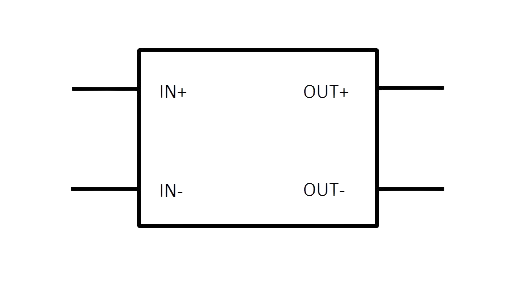
Pin Configuration and Descriptions
| Pin Number | Name | Description |
|---|---|---|
| 1 | Vin | Input voltage to the converter. Connect to the higher voltage supply. |
| 2 | GND | Ground reference for the circuit. Connect to the system ground. |
| 3 | Vout | Regulated output voltage. Connect to the load or circuit requiring lower voltage. |
| 4 | EN | Enable pin. A logic high signal here enables the converter, while a logic low disables it. |
| 5 | FB | Feedback pin. Connects to a voltage divider network for output voltage regulation. |
Usage Instructions
How to Use the Component in a Circuit
- Input Connection: Connect the positive terminal of your higher voltage source to the Vin pin, and the negative terminal to the GND pin.
- Output Connection: Connect your load to the Vout pin and the other side of the load to the GND pin.
- Enable Pin: If the converter has an enable pin (EN), connect it to a logic high level to turn on the converter. If you want to control the converter with a microcontroller, connect this pin to one of the digital I/O pins.
- Feedback Network: If the converter has a feedback pin (FB), ensure that the voltage divider connected to this pin is properly configured to set the desired output voltage.
Important Considerations and Best Practices
- Heat Dissipation: Ensure adequate cooling for the converter, as efficiency losses often result in heat generation.
- Input Capacitance: Place a sufficiently rated capacitor close to the Vin pin to stabilize the input supply voltage.
- Output Capacitance: Use a capacitor at the Vout pin to smooth out the output voltage and reduce voltage ripple.
- Inductor Selection: Choose an inductor with an appropriate current rating and low series resistance for optimal performance.
- Switching Noise: Be aware that the switching operation can generate electromagnetic interference (EMI); proper layout and filtering may be necessary.
Troubleshooting and FAQs
Common Issues
- Output Voltage Too Low or High: Check the feedback network and ensure that the resistors are of the correct value and properly connected.
- Converter Overheating: Ensure that the input voltage is within specifications and that the load does not exceed the maximum output current rating.
- Noise in the Circuit: Verify that the input and output capacitors are of adequate value and that the layout minimizes EMI.
Solutions and Tips for Troubleshooting
- Inadequate Output Voltage Regulation: Adjust the feedback resistor values or replace them if they are out of tolerance.
- Thermal Issues: Improve heat dissipation with a heatsink or by improving airflow around the converter.
- EMI Concerns: Use shielded inductors, add ferrite beads, and ensure that the PCB layout minimizes loop areas.
FAQs
Q: Can I use a step-down converter to charge batteries? A: Yes, but ensure that the output voltage and current are appropriate for the battery type and that proper charging circuitry is in place.
Q: How do I select the right inductor for my application? A: Choose an inductor with a current rating above the maximum output current and with the lowest possible series resistance.
Q: What is the purpose of the enable pin on some converters? A: The enable pin allows you to turn the converter on or off using an external control signal, which can be useful for power-saving modes.
Example Code for Arduino UNO
// Example code to control a step-down converter with an enable pin using Arduino UNO

const int enablePin = 7; // Connect the EN pin of the converter to digital pin 7

void setup() {
  pinMode(enablePin, OUTPUT); // Set the enable pin as an output
  digitalWrite(enablePin, HIGH); // Turn on the step-down converter
}

void loop() {
  // Your main code would go here
  // Use digitalWrite(enablePin, LOW) to turn off the converter if needed
}
Remember to ensure that the converter's input voltage is compatible with the source you are using and that the output voltage is suitable for the devices you are powering. Always consult the specific datasheet for your step-down converter model for precise information and limitations.