How to Use MicroView: Examples, Pinouts, and Specs
Introduction
The MicroView is a unique and innovative electronic component that combines the functionality of an Arduino-compatible microcontroller with a built-in Organic Light Emitting Diode (OLED) display. This compact module is perfect for DIY enthusiasts, educators, and professionals who need a small, yet powerful, display interface for their projects. Common applications include wearable devices, compact instruments, and any project where visual feedback is essential without the bulk of external screens.
Explore Projects Built with MicroView

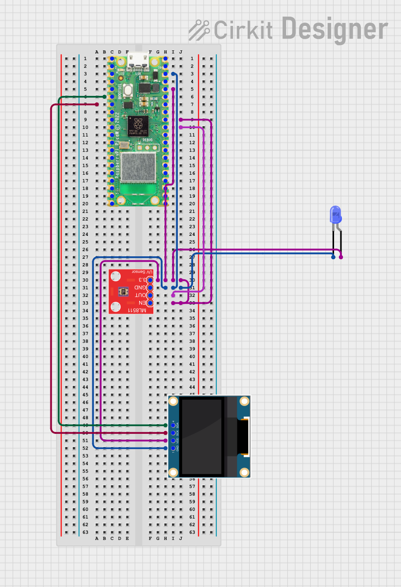
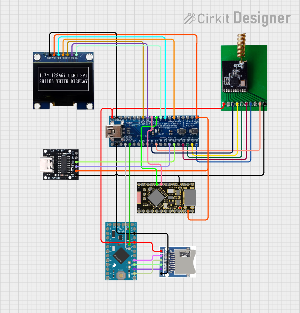
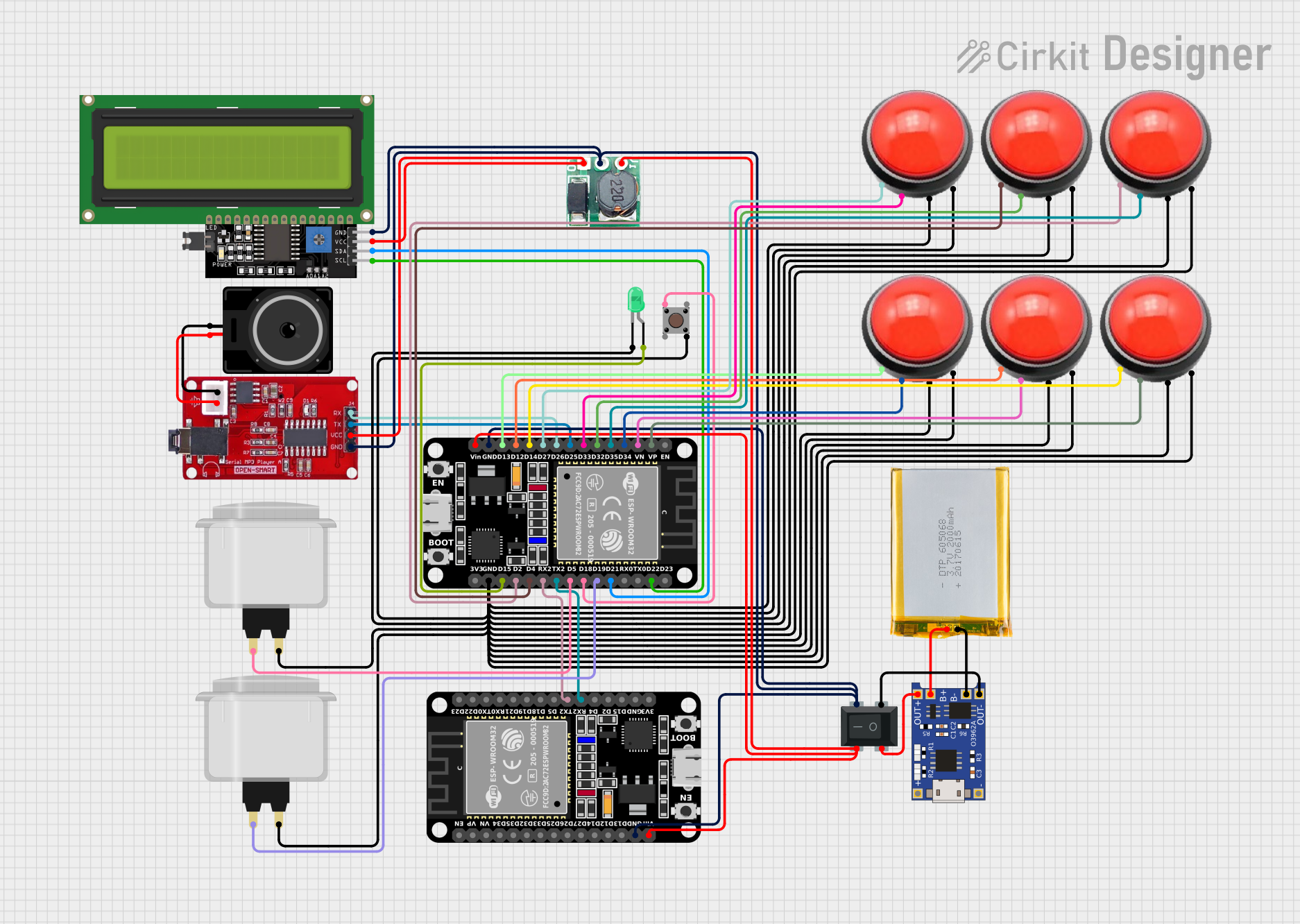
Explore Projects Built with MicroView
Technical Specifications
General Features
- Microcontroller: ATmega328P
- Clock Speed: 16 MHz
- Flash Memory: 32 KB (of which 0.5 KB used by bootloader)
- SRAM: 2 KB
- EEPROM: 1 KB
- Integrated OLED Display: 64x48 pixels
Power
- Input Voltage: 3.3V to 16V (regulated to 5V)
- Digital I/O Pins: 12 (of which 3 provide PWM output)
- Analog Input Pins: 6
- DC Current per I/O Pin: 40 mA
Pin Configuration
| Pin Number | Function | Description |
|---|---|---|
| 1 | GND | Ground |
| 2 | VIN | Voltage Input for Powering the MicroView |
| 3 | RST | Reset Pin |
| 4-9 | Digital I/O | Digital Input/Output Pins |
| 10-15 | Analog Input | Analog Input Pins |
| 16 | 5V | Regulated 5V Output |
| 17 | 3.3V | Regulated 3.3V Output |
| 18 | AREF | Analog Reference Voltage |
| 19 | GND | Ground |
Usage Instructions
Integrating MicroView into a Circuit
- Powering the MicroView: Connect a power source to the VIN and GND pins, ensuring the voltage is within the 3.3V to 16V range.
- Programming the MicroView: Use the Arduino IDE to program the MicroView, selecting the appropriate board from the Tools menu.
- Displaying Data: Utilize the MicroView library to create graphics and text on the OLED display.
Best Practices
- Always verify the power supply voltage to prevent damage to the MicroView.
- When programming, ensure that the correct drivers are installed and the board is selected in the Arduino IDE.
- Use the provided MicroView library for optimal compatibility with the OLED display.
Example Code for Arduino UNO
#include <MicroView.h>

// Initialize the MicroView object
MicroView uView;

void setup() {
  uView.begin();  // Start the MicroView
  uView.clear(PAGE);  // Clear the screen
}

void loop() {
  uView.setFontType(0);  // Set font to type 0
  uView.setCursor(0, 0); // Set cursor to top-left
  uView.print("Hello, World!"); // Print text to the screen
  uView.display(); // Refresh the screen to show the text
  delay(1000); // Wait for a second
  uView.clear(PAGE); // Clear the screen
  delay(1000); // Wait for a second
}
Troubleshooting and FAQs
Common Issues
- Display Not Lighting Up: Ensure the MicroView is correctly powered and the OLED display is properly initialized in your code.
- Garbled Display Output: Check for correct use of the MicroView library functions and ensure the refresh (
display()) command is used after drawing commands. - Unresponsive After Upload: Verify the correct board is selected in the Arduino IDE and the bootloader is functioning properly.
FAQs
Q: Can I use the MicroView with a 3.3V system? A: Yes, the MicroView can be powered with 3.3V, but ensure that the voltage does not drop below the minimum operating voltage.
Q: How do I update the firmware on the MicroView? A: Firmware updates can be done through the Arduino IDE, using the same process as uploading a sketch to an Arduino board.
Q: Is the MicroView breadboard-friendly? A: Yes, the MicroView can be used with a breadboard, but be mindful of the pin spacing and orientation when inserting it.
For further assistance, consult the MicroView community forums and the extensive documentation available online.