How to Use 63 A MCB: Examples, Pinouts, and Specs
Introduction
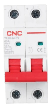
A 63 Amp Miniature Circuit Breaker (MCB) is a safety device designed to protect electrical circuits from damage caused by overcurrent, such as overloads or short circuits. It automatically interrupts the flow of electricity when the current exceeds a safe threshold, ensuring the safety of wiring, connected devices, and users. MCBs are widely used in residential, commercial, and industrial electrical systems.
Explore Projects Built with 63 A MCB


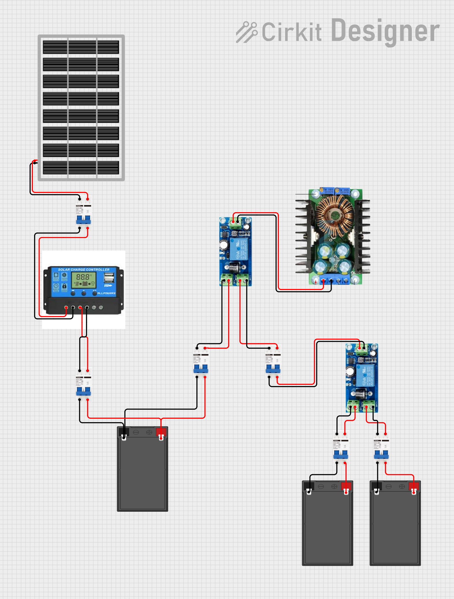

Explore Projects Built with 63 A MCB
Common Applications and Use Cases
- Protection of electrical circuits in homes, offices, and industrial facilities.
- Prevention of electrical fires caused by overcurrent or short circuits.
- Safeguarding sensitive equipment and appliances from damage due to power surges.
- Use in distribution boards for isolating and protecting individual circuits.
Technical Specifications
The following table outlines the key technical details of a 63 A MCB:
| Parameter | Specification |
|---|---|
| Rated Current (In) | 63 A |
| Rated Voltage (Un) | 230/400 V AC |
| Frequency | 50/60 Hz |
| Breaking Capacity (Icu) | 6 kA, 10 kA (varies by model) |
| Tripping Curve | B, C, or D (depending on application) |
| Number of Poles | 1P, 2P, 3P, or 4P |
| Operating Temperature | -5°C to +55°C |
| Mounting Type | DIN rail |
| Standards Compliance | IEC 60898-1, IS/IEC 60898 |
Pin Configuration and Descriptions
The 63 A MCB does not have traditional pins like electronic components but instead features terminals for connecting input and output wires. The table below describes the terminal configuration:
| Terminal | Description |
|---|---|
| Line (Input) | Connects to the incoming power supply (phase wire). |
| Load (Output) | Connects to the outgoing circuit or load. |
| Neutral | (For 2P, 3P, or 4P models) Connects to the neutral wire for balanced operation. |
Usage Instructions
How to Use the 63 A MCB in a Circuit
Select the Appropriate MCB: Choose an MCB with the correct rated current (63 A) and tripping curve (B, C, or D) based on the application.
- Curve B: For residential or light commercial use (e.g., lighting circuits).
- Curve C: For general-purpose circuits with moderate inrush currents (e.g., motors).
- Curve D: For industrial applications with high inrush currents (e.g., transformers).
Install the MCB:
- Mount the MCB on a standard DIN rail inside a distribution board.
- Ensure the MCB is securely locked into place.
Connect the Wires:
- Connect the incoming phase wire to the Line (Input) terminal.
- Connect the outgoing circuit wire to the Load (Output) terminal.
- For multi-pole MCBs, connect the neutral and additional phase wires as required.
Test the Circuit:
- After installation, switch on the MCB and verify that the connected circuit operates correctly.
- Test the tripping mechanism by simulating an overload or short circuit (if safe to do so).
Important Considerations and Best Practices
- Do Not Exceed the Rated Current: Ensure the connected load does not exceed 63 A to avoid nuisance tripping.
- Proper Wire Sizing: Use wires with an appropriate gauge to handle the current safely.
- Regular Maintenance: Periodically inspect the MCB for signs of wear, damage, or loose connections.
- Avoid Manual Reset During Faults: If the MCB trips, identify and resolve the fault before resetting it.
Arduino Integration
While MCBs are not directly connected to microcontrollers like Arduino, they can be used in circuits that power Arduino-based systems. For example, an MCB can protect the power supply feeding an Arduino project.
Troubleshooting and FAQs
Common Issues and Solutions
| Issue | Possible Cause | Solution |
|---|---|---|
| MCB trips frequently | Overloaded circuit or short circuit | Reduce the load or identify and fix the short circuit. |
| MCB does not trip during a fault | Faulty MCB or incorrect installation | Replace the MCB or verify proper wiring and connections. |
| MCB feels warm during operation | High current flow or loose connections | Ensure the load is within the rated current and tighten all connections. |
| Difficulty in resetting the MCB | Persistent fault in the circuit | Inspect the circuit for faults and resolve them before resetting the MCB. |
FAQs
Can I use a 63 A MCB for a lower current circuit?
- Yes, but it is not recommended as the MCB may not trip during lower-level faults, reducing protection.
What is the difference between B, C, and D curve MCBs?
- The tripping curve defines the MCB's response to inrush currents. Curve B trips at 3-5 times the rated current, Curve C at 5-10 times, and Curve D at 10-20 times.
Can I install an MCB without a distribution board?
- No, MCBs should always be installed in a proper enclosure or distribution board for safety.
How do I know if my MCB is faulty?
- If the MCB does not trip during a fault or trips without any apparent reason, it may be faulty and should be replaced.
By following this documentation, users can safely and effectively use a 63 A MCB to protect their electrical circuits.