Cirkit Designer Logo
Cirkit Designer
Your all-in-one circuit design IDE
Home / 
Component Documentation

How to Use Arduino UNO: Examples, Pinouts, and Specs

Image of Arduino UNO
Cirkit Designer LogoDesign with Arduino UNO in Cirkit Designer

Introduction

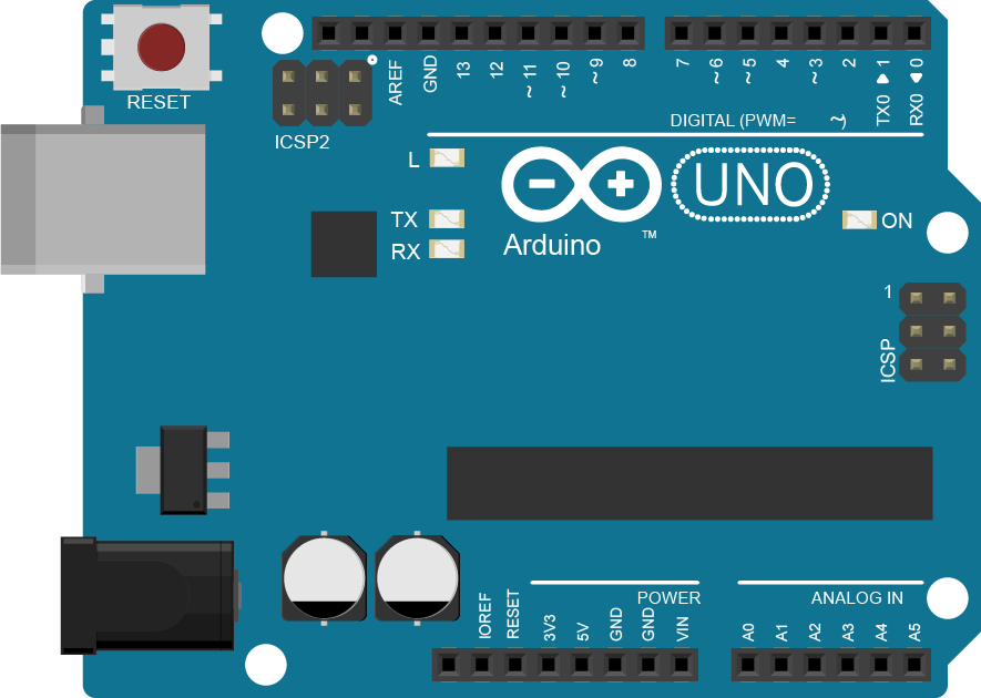
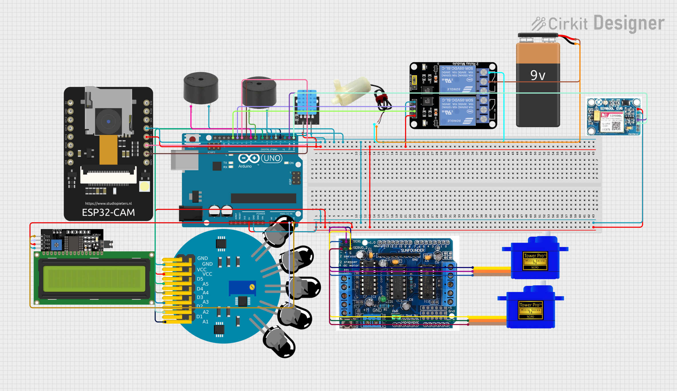
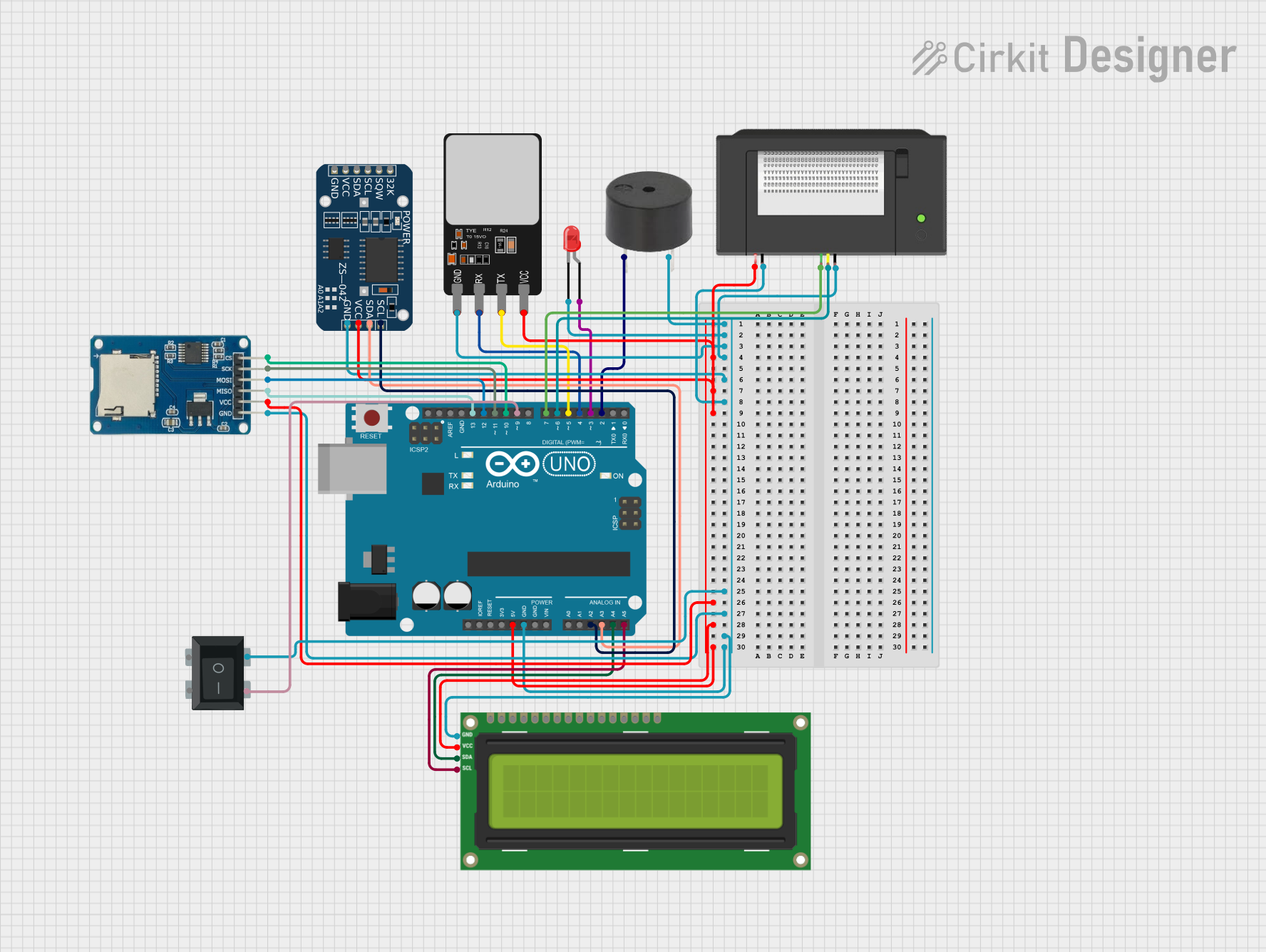
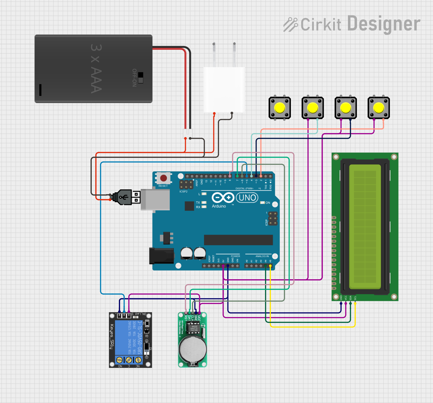
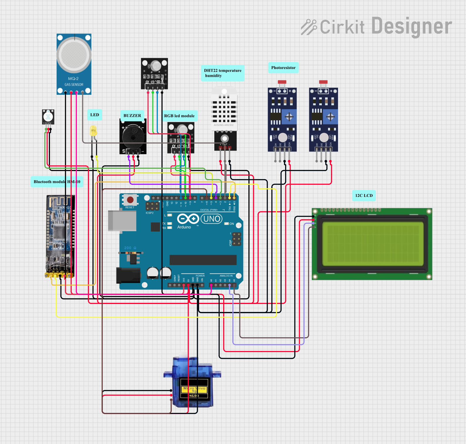
The Arduino UNO is a widely-used open-source microcontroller board based on the ATmega328P microcontroller. It is a key tool in the world of electronics prototyping due to its simplicity and flexibility. The UNO board features a range of digital and analog input/output (I/O) pins, a USB connection for programming and serial communication, a power jack for an external power source, and an In-Circuit Serial Programming (ICSP) header for flashing the bootloader.

Common applications of the Arduino UNO include:

  • DIY electronics projects
  • Educational purposes in schools and universities
  • Rapid prototyping of embedded systems
  • Robotics
  • Home automation systems
  • Interactive artworks

Explore Projects Built with Arduino UNO

Use Cirkit Designer to design, explore, and prototype these projects online. Some projects support real-time simulation. Click "Open Project" to start designing instantly!
Arduino UNO and ESP32 CAM Controlled Fire Detection and Alert System with GSM Notification
Image of ASO BOT: A project utilizing Arduino UNO in a practical application
This circuit features an Arduino UNO as the central microcontroller, interfaced with a variety of sensors, actuators, and modules. It includes a 5-channel fire sensor, temperature and humidity sensor (DHT11), two buzzers, and two servomotors controlled by an L293D driver shield. The circuit also integrates an ESP32 CAM for wireless capabilities, a 2-channel relay module controlling a mini water pump, an LCD display for user interface, a SIM 800L GSM module for cellular connectivity, and is powered by a 9V battery.
Cirkit Designer LogoOpen Project in Cirkit Designer
Arduino UNO-Based Access Control System with Data Logging
Image of Research Internal Design (2): A project utilizing Arduino UNO in a practical application
This circuit features an Arduino UNO microcontroller as the central processing unit, interfacing with a variety of peripherals. It includes a red LED, a buzzer, an I2C LCD screen, a fingerprint scanner, a thermal printer, a real-time clock (RTC) module, and a micro SD card module. The Arduino controls these components to create a multifunctional system capable of user interaction, data logging, timekeeping, and biometric input processing.
Cirkit Designer LogoOpen Project in Cirkit Designer
Arduino UNO-Based Smart Home Automation System with I2C LCD and RTC
Image of Alarm of RSU Hymn: A project utilizing Arduino UNO in a practical application
This circuit features an Arduino UNO microcontroller interfaced with a 16x2 I2C LCD for display, a DS1302 RTC for real-time clock functionality, and a 1-channel relay for controlling high-power devices. Additionally, it includes multiple pushbuttons for user input and is powered by a 3xAAA battery pack, USB power, or a 5V adapter.
Cirkit Designer LogoOpen Project in Cirkit Designer
Arduino UNO-Based Smart Home Automation System with Bluetooth Control
Image of WORK_1: A project utilizing Arduino UNO in a practical application
This circuit uses an Arduino UNO to control various components including a servo motor, an LED, an RGB LED, a buzzer, and an LCD display based on inputs from a photoresistor, a DHT22 temperature and humidity sensor, and an MQ-2 gas sensor. Additionally, a Bluetooth module allows for remote control via a mobile application.
Cirkit Designer LogoOpen Project in Cirkit Designer

Explore Projects Built with Arduino UNO

Use Cirkit Designer to design, explore, and prototype these projects online. Some projects support real-time simulation. Click "Open Project" to start designing instantly!
Image of ASO BOT: A project utilizing Arduino UNO in a practical application
Arduino UNO and ESP32 CAM Controlled Fire Detection and Alert System with GSM Notification
This circuit features an Arduino UNO as the central microcontroller, interfaced with a variety of sensors, actuators, and modules. It includes a 5-channel fire sensor, temperature and humidity sensor (DHT11), two buzzers, and two servomotors controlled by an L293D driver shield. The circuit also integrates an ESP32 CAM for wireless capabilities, a 2-channel relay module controlling a mini water pump, an LCD display for user interface, a SIM 800L GSM module for cellular connectivity, and is powered by a 9V battery.
Cirkit Designer LogoOpen Project in Cirkit Designer
Image of Research Internal Design (2): A project utilizing Arduino UNO in a practical application
Arduino UNO-Based Access Control System with Data Logging
This circuit features an Arduino UNO microcontroller as the central processing unit, interfacing with a variety of peripherals. It includes a red LED, a buzzer, an I2C LCD screen, a fingerprint scanner, a thermal printer, a real-time clock (RTC) module, and a micro SD card module. The Arduino controls these components to create a multifunctional system capable of user interaction, data logging, timekeeping, and biometric input processing.
Cirkit Designer LogoOpen Project in Cirkit Designer
Image of Alarm of RSU Hymn: A project utilizing Arduino UNO in a practical application
Arduino UNO-Based Smart Home Automation System with I2C LCD and RTC
This circuit features an Arduino UNO microcontroller interfaced with a 16x2 I2C LCD for display, a DS1302 RTC for real-time clock functionality, and a 1-channel relay for controlling high-power devices. Additionally, it includes multiple pushbuttons for user input and is powered by a 3xAAA battery pack, USB power, or a 5V adapter.
Cirkit Designer LogoOpen Project in Cirkit Designer
Image of WORK_1: A project utilizing Arduino UNO in a practical application
Arduino UNO-Based Smart Home Automation System with Bluetooth Control
This circuit uses an Arduino UNO to control various components including a servo motor, an LED, an RGB LED, a buzzer, and an LCD display based on inputs from a photoresistor, a DHT22 temperature and humidity sensor, and an MQ-2 gas sensor. Additionally, a Bluetooth module allows for remote control via a mobile application.
Cirkit Designer LogoOpen Project in Cirkit Designer

Technical Specifications

Key Technical Details

  • Microcontroller: ATmega328P
  • Operating Voltage: 5V
  • Input Voltage (recommended): 7-12V
  • Input Voltage (limit): 6-20V
  • Digital I/O Pins: 14 (of which 6 provide PWM output)
  • Analog Input Pins: 6
  • DC Current per I/O Pin: 20 mA
  • DC Current for 3.3V Pin: 50 mA
  • Flash Memory: 32 KB (ATmega328P) of which 0.5 KB used by bootloader
  • SRAM: 2 KB (ATmega328P)
  • EEPROM: 1 KB (ATmega328P)
  • Clock Speed: 16 MHz
  • LED_BUILTIN: Pin 13

Pin Configuration and Descriptions

Pin Number Function Description
1-13 Digital I/O Digital pins which can be used as input or output
14-19 Analog Input Analog pins which can be used to read analog voltages
A0-A5 Analog Channels Same as pins 14-19
0 (RX) Serial Receive Used to receive serial data
1 (TX) Serial Transmit Used to transmit serial data
2-13 PWM Provide 8-bit PWM output with the analogWrite() function
13 LED_BUILTIN Connected to the onboard LED
GND Ground Ground pins
AREF Analog Reference Used to set an external reference voltage
3.3V Supplies 3.3V output
5V Supplies 5V output
VIN Input voltage to Arduino when using an external power source

Usage Instructions

How to Use the Arduino UNO in a Circuit

  1. Connecting Power: The Arduino UNO can be powered via the USB connection or with an external power supply. The power source is selected automatically.
  2. Using Digital I/O Pins: Configure the pins as INPUT or OUTPUT using the pinMode() function. Use digitalWrite() to set the pin to HIGH or LOW, or digitalRead() to read the state of the pin.
  3. Using Analog Input Pins: Read analog voltages using the analogRead() function, which returns a value from 0 to 1023.
  4. Using PWM Pins: Generate a PWM signal using analogWrite() on pins marked with PWM.

Important Considerations and Best Practices

  • Do not exceed the voltage and current ratings of the I/O pins to prevent damage.
  • Use a current-limiting resistor when connecting LEDs to digital pins.
  • Ensure that the power supply used is within the recommended voltage range.
  • When using external components, consider the total current draw to avoid overloading the voltage regulator.

Troubleshooting and FAQs

Common Issues

  • Arduino not recognized by computer: Check the USB cable and drivers.
  • Sketch not uploading: Ensure the correct board and port are selected in the IDE.
  • Unexpected behavior in circuits: Verify connections and power supply voltages.

Solutions and Tips for Troubleshooting

  • Reset the board by pressing the reset button.
  • Double-check wiring against the circuit diagram.
  • Use serial print statements to debug code.
  • Ensure that the bootloader is correctly flashed.

FAQs

Q: Can I use the Arduino UNO with a higher voltage power supply? A: The recommended input voltage is 7-12V, but the limit is 6-20V. Exceeding 12V may cause the voltage regulator to overheat and damage the board.

Q: How many devices can I connect to the Arduino UNO? A: It depends on the power consumption and I/O requirements of the devices. Ensure the total current does not exceed the board's limits.

Q: Can I program the Arduino UNO without using the Arduino IDE? A: Yes, you can use alternative IDEs or command-line tools, but the Arduino IDE is the simplest method for beginners.

Example Code for Arduino UNO

Here is a simple example of blinking the onboard LED connected to pin 13:

// Define the LED pin
const int ledPin = 13;

// The setup function runs once when you press reset or power the board
void setup() {
  // Initialize the digital pin as an output.
  pinMode(ledPin, OUTPUT);
}

// The loop function runs over and over again forever
void loop() {
  digitalWrite(ledPin, HIGH);   // Turn the LED on
  delay(1000);                  // Wait for a second
  digitalWrite(ledPin, LOW);    // Turn the LED off
  delay(1000);                  // Wait for a second
}

This code will blink the onboard LED every second. It's a great starting point for understanding how to control digital outputs on the Arduino UNO.