Cirkit Designer Logo
Cirkit Designer
Your all-in-one circuit design IDE
Home / 
Component Documentation

How to Use DS3231 RTC Module with EEPROM: Examples, Pinouts, and Specs

Image of DS3231 RTC Module with EEPROM
Cirkit Designer LogoDesign with DS3231 RTC Module with EEPROM in Cirkit Designer

Introduction

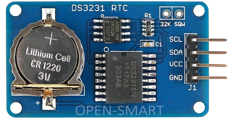
The DS3231 is a highly accurate real-time clock (RTC) module designed to maintain time and date information even when the main power supply is disconnected, thanks to its onboard backup battery. It features an integrated EEPROM for non-volatile data storage, making it ideal for applications requiring both timekeeping and persistent data retention. The module communicates via the I2C protocol and includes temperature compensation to ensure consistent accuracy across a wide range of operating conditions.

Explore Projects Built with DS3231 RTC Module with EEPROM

Use Cirkit Designer to design, explore, and prototype these projects online. Some projects support real-time simulation. Click "Open Project" to start designing instantly!
Dual RTC DS3231 Synchronization with Glyph C3 Microcontroller
Image of DS: A project utilizing DS3231 RTC Module with EEPROM in a practical application
This circuit integrates two RTC DS3231 real-time clock modules with a Glyph C3 microcontroller. The RTC modules are connected to the microcontroller via I2C communication protocol, using the SCL and SDA lines for clock and data respectively. Both RTC modules and the microcontroller share a common power supply (3V3) and ground (GND), indicating that they operate at the same voltage level.
Cirkit Designer LogoOpen Project in Cirkit Designer
ESP32-Based Real-Time Clock Synchronization
Image of RTC: A project utilizing DS3231 RTC Module with EEPROM in a practical application
This circuit connects an ESP32 microcontroller to a DS3231 Real Time Clock (RTC) module. The ESP32's Vin and GND pins are connected to the VCC and GND pins of the DS3231, providing power to the RTC. The SCL and SDA pins of the DS3231 are connected to the D22 and D21 pins of the ESP32, respectively, enabling I2C communication between the microcontroller and the RTC module.
Cirkit Designer LogoOpen Project in Cirkit Designer
NodeMCU ESP8266 Based Smart Relay with LCD Interface and RTC Support
Image of IoT based bell system: A project utilizing DS3231 RTC Module with EEPROM in a practical application
This circuit features a NodeMCU V3 ESP8266 microcontroller connected to a KY-019 Relay module for controlling power to a device, a DS3231 Real Time Clock (RTC) for timekeeping, and an LCM1602 IIC module interfaced with an LCD Display for user interface. The circuit is powered by a Mini AC-DC converter module that steps down AC mains to 5V, and the NodeMCU facilitates communication between the RTC, the relay, and the display, likely for scheduling and displaying the status of the connected device.
Cirkit Designer LogoOpen Project in Cirkit Designer
ESP32 Mini-Based Smart Timekeeper with OLED Display and Battery Charging
Image of RM Gloves: A project utilizing DS3231 RTC Module with EEPROM in a practical application
This circuit features an ESP32 Mini microcontroller as its core, interfaced with a 0.96" OLED display and a DS3231 Real-Time Clock (RTC) for timekeeping and display purposes. A TP4056 module is used for charging a LiPoly battery, which powers the system through an LM2596 voltage regulator and an AMS1117-3.3 voltage regulator to step down and stabilize the voltage for the ESP32 and peripherals. User inputs are captured through a rotary potentiometer and a red pushbutton, which are connected to the ESP32's GPIOs for control and reset functionality.
Cirkit Designer LogoOpen Project in Cirkit Designer

Explore Projects Built with DS3231 RTC Module with EEPROM

Use Cirkit Designer to design, explore, and prototype these projects online. Some projects support real-time simulation. Click "Open Project" to start designing instantly!
Image of DS: A project utilizing DS3231 RTC Module with EEPROM in a practical application
Dual RTC DS3231 Synchronization with Glyph C3 Microcontroller
This circuit integrates two RTC DS3231 real-time clock modules with a Glyph C3 microcontroller. The RTC modules are connected to the microcontroller via I2C communication protocol, using the SCL and SDA lines for clock and data respectively. Both RTC modules and the microcontroller share a common power supply (3V3) and ground (GND), indicating that they operate at the same voltage level.
Cirkit Designer LogoOpen Project in Cirkit Designer
Image of RTC: A project utilizing DS3231 RTC Module with EEPROM in a practical application
ESP32-Based Real-Time Clock Synchronization
This circuit connects an ESP32 microcontroller to a DS3231 Real Time Clock (RTC) module. The ESP32's Vin and GND pins are connected to the VCC and GND pins of the DS3231, providing power to the RTC. The SCL and SDA pins of the DS3231 are connected to the D22 and D21 pins of the ESP32, respectively, enabling I2C communication between the microcontroller and the RTC module.
Cirkit Designer LogoOpen Project in Cirkit Designer
Image of IoT based bell system: A project utilizing DS3231 RTC Module with EEPROM in a practical application
NodeMCU ESP8266 Based Smart Relay with LCD Interface and RTC Support
This circuit features a NodeMCU V3 ESP8266 microcontroller connected to a KY-019 Relay module for controlling power to a device, a DS3231 Real Time Clock (RTC) for timekeeping, and an LCM1602 IIC module interfaced with an LCD Display for user interface. The circuit is powered by a Mini AC-DC converter module that steps down AC mains to 5V, and the NodeMCU facilitates communication between the RTC, the relay, and the display, likely for scheduling and displaying the status of the connected device.
Cirkit Designer LogoOpen Project in Cirkit Designer
Image of RM Gloves: A project utilizing DS3231 RTC Module with EEPROM in a practical application
ESP32 Mini-Based Smart Timekeeper with OLED Display and Battery Charging
This circuit features an ESP32 Mini microcontroller as its core, interfaced with a 0.96" OLED display and a DS3231 Real-Time Clock (RTC) for timekeeping and display purposes. A TP4056 module is used for charging a LiPoly battery, which powers the system through an LM2596 voltage regulator and an AMS1117-3.3 voltage regulator to step down and stabilize the voltage for the ESP32 and peripherals. User inputs are captured through a rotary potentiometer and a red pushbutton, which are connected to the ESP32's GPIOs for control and reset functionality.
Cirkit Designer LogoOpen Project in Cirkit Designer

Common Applications and Use Cases

  • Data logging systems
  • Alarm clocks and timers
  • IoT devices requiring time synchronization
  • Event scheduling in embedded systems
  • Persistent storage for configuration data or logs

Technical Specifications

Key Technical Details

Parameter Specification
Supply Voltage 3.3V to 5.5V
Backup Battery Voltage 2.3V to 3.7V (CR2032 recommended)
Timekeeping Accuracy ±2 ppm from 0°C to +40°C
Communication Protocol I2C (7-bit address: 0x68)
EEPROM Capacity 32 KB (256 Kbit)
Operating Temperature Range -40°C to +85°C
Oscillator Built-in temperature-compensated crystal oscillator (TCXO)

Pin Configuration and Descriptions

Pin Name Pin Number Description
GND 1 Ground connection
VCC 2 Power supply (3.3V to 5.5V)
SDA 3 I2C data line
SCL 4 I2C clock line
SQW 5 Square wave output (optional, programmable frequency)
32K 6 32.768 kHz output (optional)

Usage Instructions

How to Use the DS3231 RTC Module in a Circuit

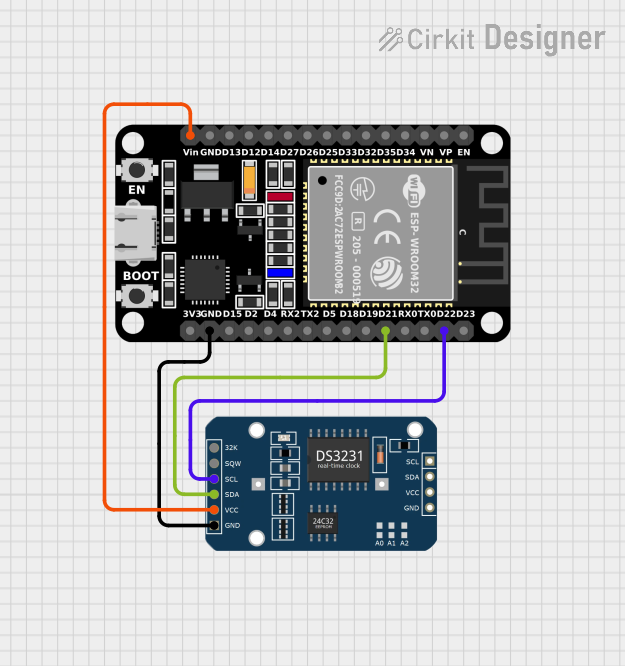
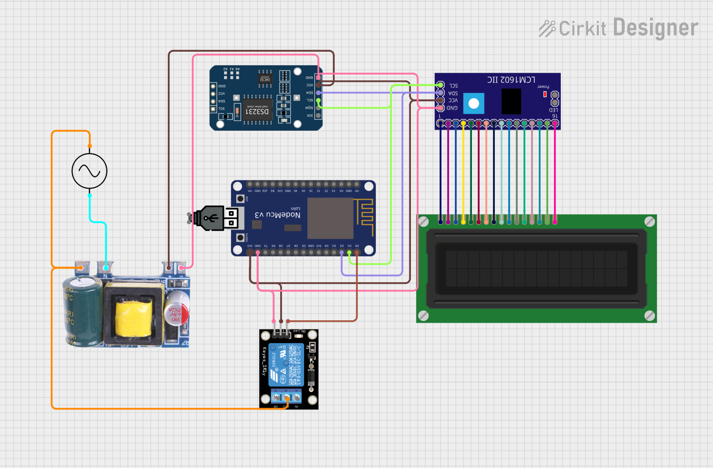
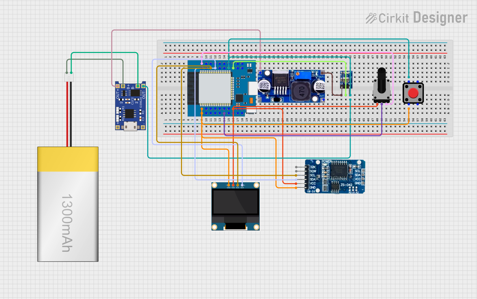
  1. Power the Module: Connect the VCC pin to a 3.3V or 5V power source and the GND pin to ground.
  2. I2C Communication: Connect the SDA and SCL pins to the corresponding I2C pins on your microcontroller (e.g., Arduino UNO: A4 for SDA and A5 for SCL).
  3. Backup Battery: Insert a CR2032 coin cell battery into the battery holder to maintain timekeeping during power loss.
  4. Optional Outputs: Use the SQW pin for a programmable square wave signal or the 32K pin for a 32.768 kHz clock signal if required.

Important Considerations and Best Practices

  • Ensure pull-up resistors (typically 4.7kΩ) are connected to the SDA and SCL lines if not already present on the module.
  • Avoid shorting the backup battery terminals to prevent damage.
  • Use a decoupling capacitor (e.g., 0.1 µF) near the VCC pin to reduce noise.
  • When using the EEPROM, ensure proper I2C addressing to avoid overwriting critical data.

Example Code for Arduino UNO

Below is an example of how to interface the DS3231 RTC module with an Arduino UNO to read the current time and date:

#include <Wire.h>
#include <RTClib.h> // Install the RTClib library via Arduino Library Manager

RTC_DS3231 rtc; // Create an RTC object

void setup() {
  Serial.begin(9600); // Initialize serial communication
  Wire.begin();       // Initialize I2C communication

  if (!rtc.begin()) {
    Serial.println("Couldn't find RTC module. Check connections.");
    while (1); // Halt execution if RTC is not detected
  }

  if (rtc.lostPower()) {
    Serial.println("RTC lost power, setting the time...");
    // Set the RTC to the current date and time
    rtc.adjust(DateTime(F(__DATE__), F(__TIME__)));
  }
}

void loop() {
  DateTime now = rtc.now(); // Get the current date and time

  // Print the current date and time to the Serial Monitor
  Serial.print(now.year(), DEC);
  Serial.print('/');
  Serial.print(now.month(), DEC);
  Serial.print('/');
  Serial.print(now.day(), DEC);
  Serial.print(" ");
  Serial.print(now.hour(), DEC);
  Serial.print(':');
  Serial.print(now.minute(), DEC);
  Serial.print(':');
  Serial.print(now.second(), DEC);
  Serial.println();

  delay(1000); // Wait for 1 second before updating
}

Notes on the Code

  • The RTClib library simplifies communication with the DS3231 module.
  • The rtc.adjust() function sets the RTC to the current system time during the first run or if power is lost.
  • Modify the code to include additional functionality, such as alarms or EEPROM usage, as needed.

Troubleshooting and FAQs

Common Issues and Solutions

  1. RTC Not Detected

    • Cause: Incorrect wiring or missing pull-up resistors on the I2C lines.
    • Solution: Double-check the connections and ensure pull-up resistors are in place.
  2. Incorrect Time or Date

    • Cause: RTC lost power or was not initialized properly.
    • Solution: Use the rtc.adjust() function to set the correct time and date.
  3. EEPROM Data Corruption

    • Cause: Improper I2C addressing or power interruptions during write operations.
    • Solution: Verify the I2C address and ensure stable power during EEPROM writes.
  4. Square Wave Output Not Working

    • Cause: SQW pin not configured or incorrect frequency setting.
    • Solution: Use the appropriate library functions to configure the square wave output.

FAQs

Q: Can the DS3231 module operate without a backup battery?
A: Yes, but it will lose timekeeping functionality when the main power is disconnected.

Q: How accurate is the DS3231 RTC module?
A: The module has an accuracy of ±2 ppm from 0°C to +40°C, equivalent to a drift of about 1 minute per year.

Q: Can I use the EEPROM independently of the RTC?
A: Yes, the EEPROM can be accessed via I2C for general-purpose data storage, independent of the RTC functionality.

Q: What is the maximum I2C clock speed supported by the DS3231?
A: The DS3231 supports I2C clock speeds up to 400 kHz (Fast Mode).