How to Use led: Examples, Pinouts, and Specs
Introduction
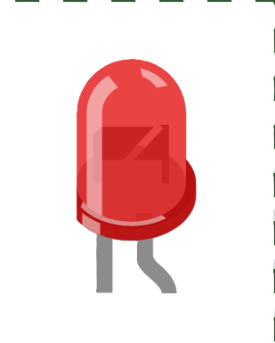
A Light Emitting Diode (LED) is a semiconductor device that emits light when an electric current passes through it. LEDs are energy-efficient and have a long lifespan, making them popular for various lighting applications. They are widely used in indicators, displays, backlighting, and general-purpose lighting. LEDs are available in various colors, sizes, and shapes, making them versatile for numerous applications.
Common applications of LEDs include:
- Status indicators on electronic devices
- Backlighting for LCD screens
- Decorative and architectural lighting
- Automotive lighting (e.g., brake lights, headlights)
- Signal and traffic lights
- Flashlights and portable lighting devices
Explore Projects Built with led

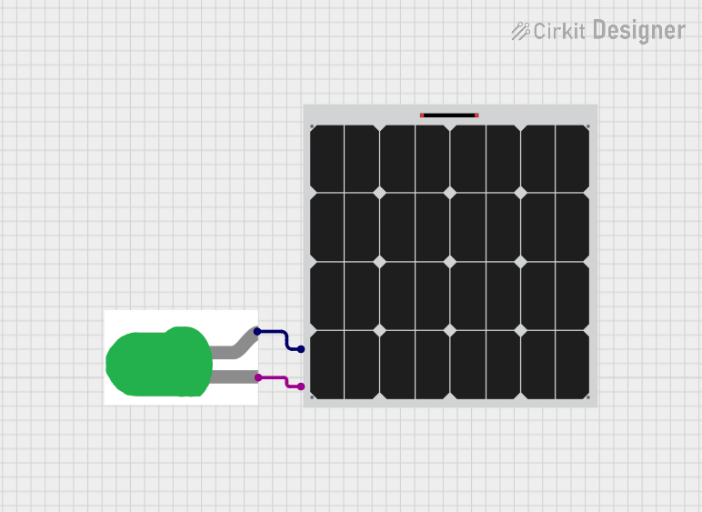
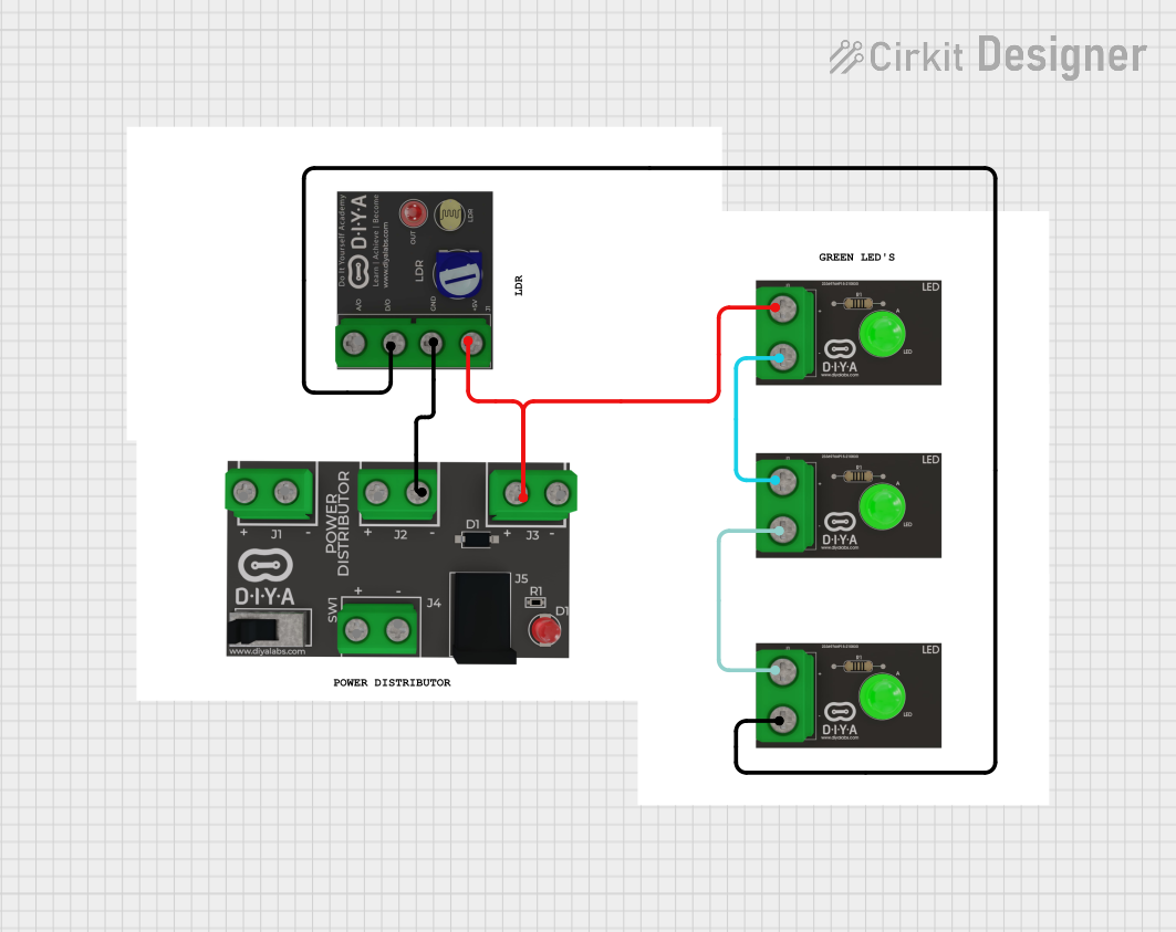
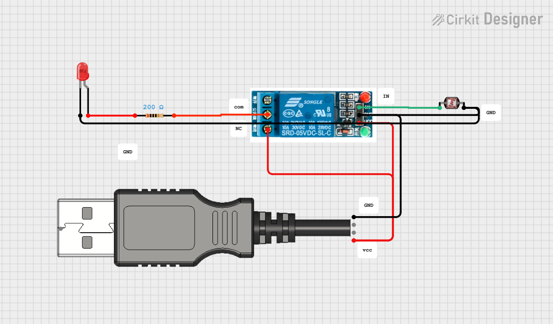
Explore Projects Built with led
Technical Specifications
Below are the general technical specifications for a standard 5mm LED. Note that specifications may vary depending on the specific type and manufacturer.
| Parameter | Value |
|---|---|
| Forward Voltage (Vf) | 1.8V - 3.3V (varies by color) |
| Forward Current (If) | 10mA - 20mA (typical) |
| Maximum Current (Imax) | 30mA (varies by model) |
| Power Dissipation | 60mW (typical) |
| Wavelength (Color) | 400nm - 700nm (visible spectrum) |
| Viewing Angle | 20° - 60° (varies by design) |
| Reverse Voltage (Vr) | 5V (maximum) |
| Operating Temperature | -40°C to +85°C |
Pin Configuration
A standard LED has two pins:
| Pin | Description |
|---|---|
| Anode (+) | The longer leg of the LED. Connect this to the positive terminal of the power supply. |
| Cathode (-) | The shorter leg of the LED. Connect this to the negative terminal or ground. |
Usage Instructions
How to Use an LED in a Circuit
Determine the Forward Voltage and Current: Check the LED's datasheet for its forward voltage (Vf) and forward current (If). For example, a red LED typically has a forward voltage of 2V and a forward current of 20mA.
Calculate the Resistor Value: To prevent damage to the LED, use a current-limiting resistor. The resistor value can be calculated using Ohm's Law: [ R = \frac{V_{supply} - V_f}{I_f} ] Where:
- ( V_{supply} ) is the supply voltage
- ( V_f ) is the forward voltage of the LED
- ( I_f ) is the forward current of the LED (in amperes)
For example, if ( V_{supply} = 5V ), ( V_f = 2V ), and ( I_f = 20mA ): [ R = \frac{5V - 2V}{0.02A} = 150\Omega ]
Connect the LED:
- Connect the anode (+) of the LED to the positive terminal of the power supply through the resistor.
- Connect the cathode (-) of the LED to the ground.
Test the Circuit: Power on the circuit and verify that the LED lights up. If it does not, check the polarity and connections.
Example: Connecting an LED to an Arduino UNO
Below is an example of how to connect and control an LED using an Arduino UNO.
Circuit Diagram
- Connect the anode (+) of the LED to Arduino pin 13 through a 220Ω resistor.
- Connect the cathode (-) of the LED to the GND pin of the Arduino.
Arduino Code
// LED Blink Example
// This code blinks an LED connected to pin 13 of the Arduino UNO.
// Ensure a 220Ω resistor is used to limit current through the LED.

void setup() {
  pinMode(13, OUTPUT); // Set pin 13 as an output pin
}

void loop() {
  digitalWrite(13, HIGH); // Turn the LED on
  delay(1000);            // Wait for 1 second
  digitalWrite(13, LOW);  // Turn the LED off
  delay(1000);            // Wait for 1 second
}
Important Considerations
- Polarity: LEDs are polarized components. Ensure the anode and cathode are connected correctly.
- Current Limiting: Always use a resistor to limit the current through the LED. Exceeding the maximum current can damage the LED.
- Heat Dissipation: While LEDs are efficient, high-power LEDs may require heat sinks to dissipate heat.
Troubleshooting and FAQs
Common Issues
LED Does Not Light Up:
- Check the polarity of the LED. Ensure the anode is connected to the positive terminal and the cathode to the ground.
- Verify the resistor value. A resistor with too high a value may prevent the LED from lighting up.
- Ensure the power supply voltage is sufficient to exceed the LED's forward voltage.
LED is Dim:
- The resistor value may be too high, limiting the current excessively.
- The power supply voltage may be too low.
LED Burns Out:
- The current through the LED may have exceeded its maximum rating. Always use a current-limiting resistor.
- Check for voltage spikes in the circuit.
Flickering LED:
- This may be caused by an unstable power supply or loose connections.
FAQs
Q: Can I connect an LED directly to a battery?
A: No, connecting an LED directly to a battery without a resistor can cause excessive current to flow through the LED, potentially damaging it.
Q: How do I choose the right resistor for my LED?
A: Use the formula ( R = \frac{V_{supply} - V_f}{I_f} ) to calculate the resistor value. Always round up to the nearest standard resistor value.
Q: Can I use an LED with an AC power source?
A: LEDs are designed for DC operation. To use an LED with AC power, you need additional components such as a rectifier and a current-limiting resistor.
Q: What is the lifespan of an LED?
A: LEDs typically have a lifespan of 25,000 to 50,000 hours, depending on usage and operating conditions.
By following this documentation, you can effectively use LEDs in your projects while avoiding common pitfalls.