
How to Use Fan 1: Examples, Pinouts, and Specs
 Design with Fan 1 in Cirkit Designer
Introduction
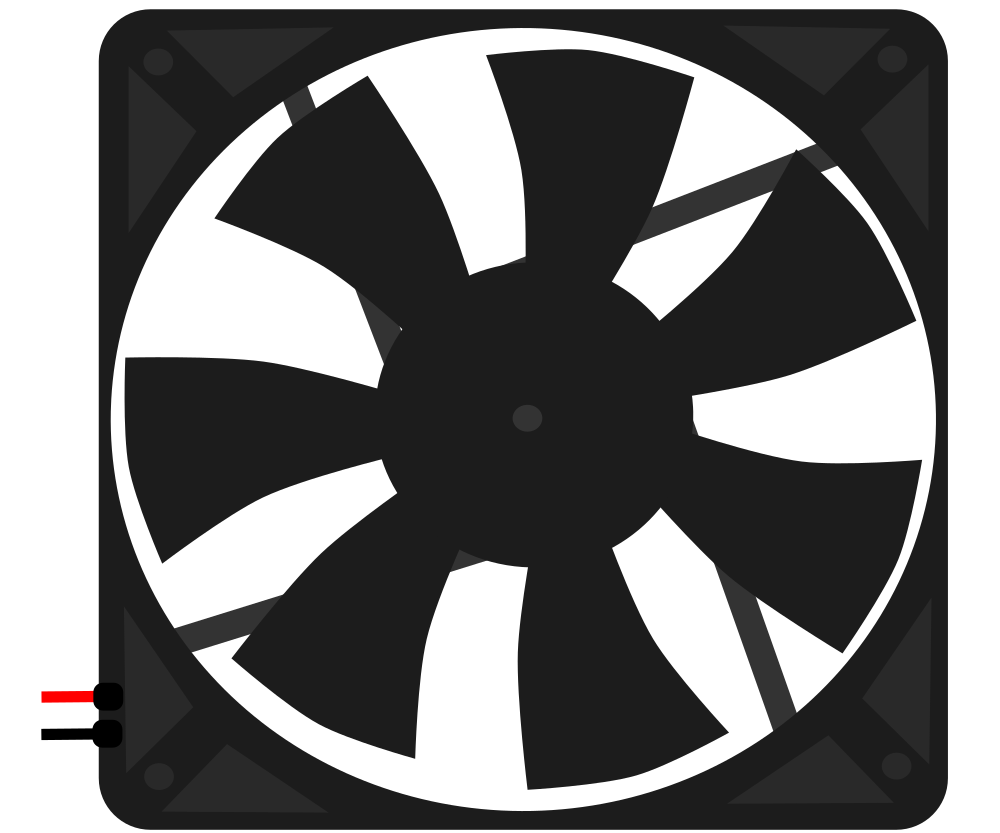
Fan 1 is a compact and efficient device designed to create airflow by rotating its blades. It is commonly used for cooling or ventilation purposes in electronic circuits, ensuring that components such as microcontrollers, power supplies, and other heat-sensitive devices operate within safe temperature ranges. Its small size and low power consumption make it ideal for integration into a variety of projects, from DIY electronics to industrial applications.
Explore Projects Built with Fan 1
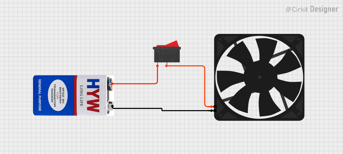 Open Project in Cirkit Designer
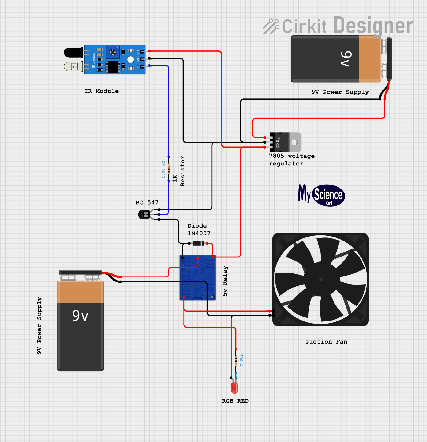 Open Project in Cirkit Designer
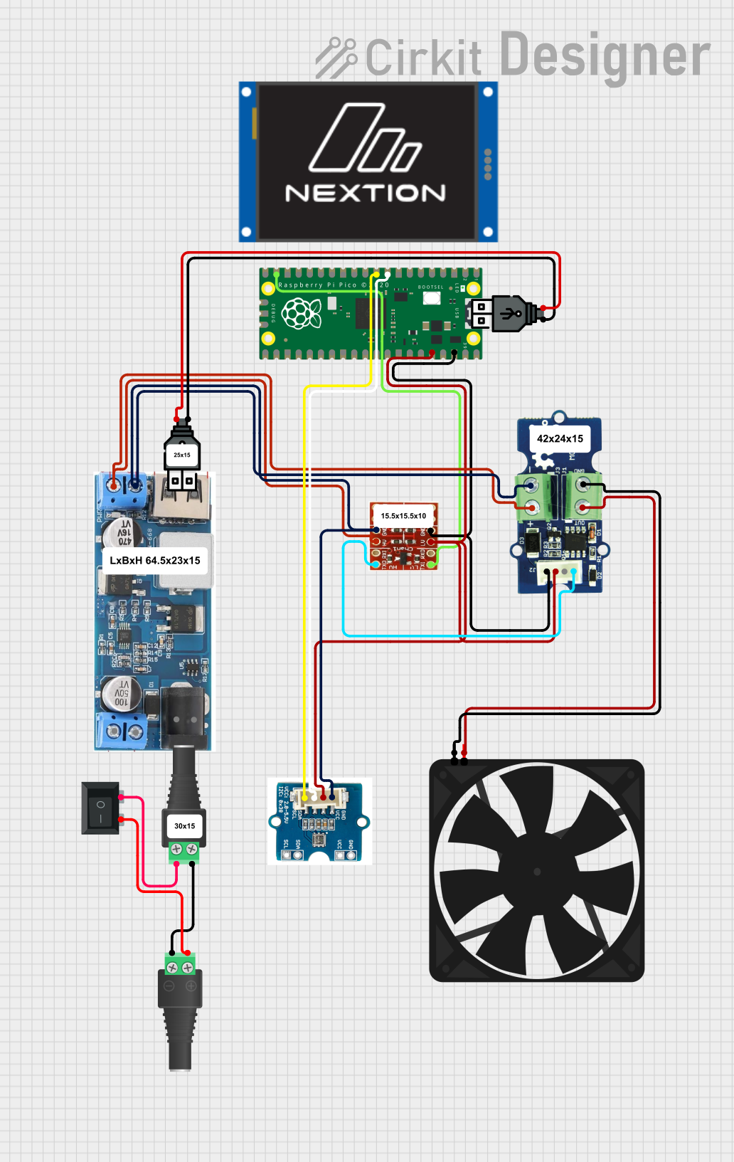 Open Project in Cirkit Designer
 Open Project in Cirkit Designer
Explore Projects Built with Fan 1
Open Project in Cirkit DesignerOpen Project in Cirkit DesignerOpen Project in Cirkit DesignerOpen Project in Cirkit DesignerCommon Applications
- Cooling microcontrollers, processors, and power supplies
- Ventilation in enclosures or cases
- Heat dissipation in robotics and automation systems
- Airflow management in 3D printers and other machinery
Technical Specifications
Key Specifications
| Parameter | Value |
|---|---|
| Operating Voltage | 5V DC |
| Operating Current | 100mA |
| Power Consumption | 0.5W |
| Airflow | 5 CFM (Cubic Feet per Minute) |
| Dimensions | 40mm x 40mm x 10mm |
| Connector Type | 2-pin JST |
| Noise Level | 25 dBA |
| Bearing Type | Sleeve Bearing |
| Lifespan | 30,000 hours |
Pin Configuration
| Pin Number | Pin Name | Description |
|---|---|---|
| 1 | VCC | Positive power supply (5V DC) |
| 2 | GND | Ground connection |
Usage Instructions
How to Use Fan 1 in a Circuit
- Power Connection: Connect the VCC pin of the fan to a 5V DC power source and the GND pin to the ground of your circuit.
- Placement: Position the fan near the heat source or within the enclosure to ensure optimal airflow. Make sure the airflow direction aligns with your cooling requirements.
- Mounting: Use screws or adhesive mounts to secure the fan in place. Ensure that the blades are unobstructed for efficient operation.
- Control (Optional): If you want to control the fan speed, you can use a PWM (Pulse Width Modulation) signal from a microcontroller like an Arduino.
Important Considerations
- Voltage Compatibility: Ensure that the fan is powered with a stable 5V DC supply. Exceeding the voltage rating may damage the fan.
- Airflow Direction: Check the markings on the fan housing to identify the airflow direction and blade rotation.
- Noise Reduction: To minimize noise, avoid placing the fan too close to other components or obstructions.
- Heat Dissipation: Ensure that the fan is used in conjunction with proper heat sinks for maximum cooling efficiency.
Example: Controlling Fan 1 with an Arduino UNO
Below is an example of how to control Fan 1 using an Arduino UNO and a transistor for PWM speed control.
// Example: Controlling Fan 1 speed with Arduino UNO
// Connect the fan's VCC to the collector of an NPN transistor
// Connect the fan's GND to the Arduino GND
// Use a PWM pin (e.g., pin 9) to control the transistor's base via a resistor

const int fanPin = 9; // PWM pin connected to the transistor's base

void setup() {
  pinMode(fanPin, OUTPUT); // Set the fan control pin as output
}

void loop() {
  analogWrite(fanPin, 128); // Set fan speed to 50% (128 out of 255)
  delay(5000); // Run at 50% speed for 5 seconds

  analogWrite(fanPin, 255); // Set fan speed to 100% (255 out of 255)
  delay(5000); // Run at full speed for 5 seconds

  analogWrite(fanPin, 0); // Turn off the fan
  delay(5000); // Fan off for 5 seconds
}
Troubleshooting and FAQs
Common Issues and Solutions
Fan Does Not Spin
- Cause: No power supply or incorrect wiring.
- Solution: Verify that the VCC and GND pins are correctly connected to a 5V DC power source.
Fan Spins Slowly
- Cause: Insufficient voltage or current.
- Solution: Ensure the power supply can provide at least 100mA at 5V DC.
Excessive Noise
- Cause: Obstructions near the fan blades or improper mounting.
- Solution: Clear any obstructions and ensure the fan is securely mounted.
Overheating Components
- Cause: Inadequate airflow or incorrect fan placement.
- Solution: Reposition the fan closer to the heat source and ensure proper airflow direction.
FAQs
Q: Can I use Fan 1 with a 12V power supply?
A: No, Fan 1 is designed for 5V DC operation. Using a higher voltage may damage the fan.Q: How do I know the airflow direction?
A: The fan housing typically has arrows indicating the airflow direction and blade rotation.Q: Can I control the fan speed without a microcontroller?
A: Yes, you can use a variable resistor or a dedicated fan speed controller circuit.Q: Is Fan 1 suitable for outdoor use?
A: No, Fan 1 is not weatherproof and should only be used in indoor or protected environments.