How to Use stm32 bluepill: Examples, Pinouts, and Specs
Introduction
The STM32 Blue Pill is a compact and cost-effective development board designed by STM32. It features the STM32F103C8T6 microcontroller, which is based on the ARM Cortex-M3 architecture. This board is widely used in prototyping, embedded systems, and IoT projects due to its powerful 32-bit processing capabilities, extensive I/O options, and compatibility with various programming environments.
Explore Projects Built with stm32 bluepill
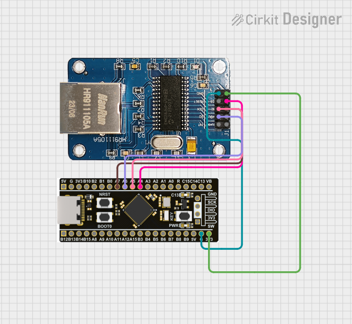

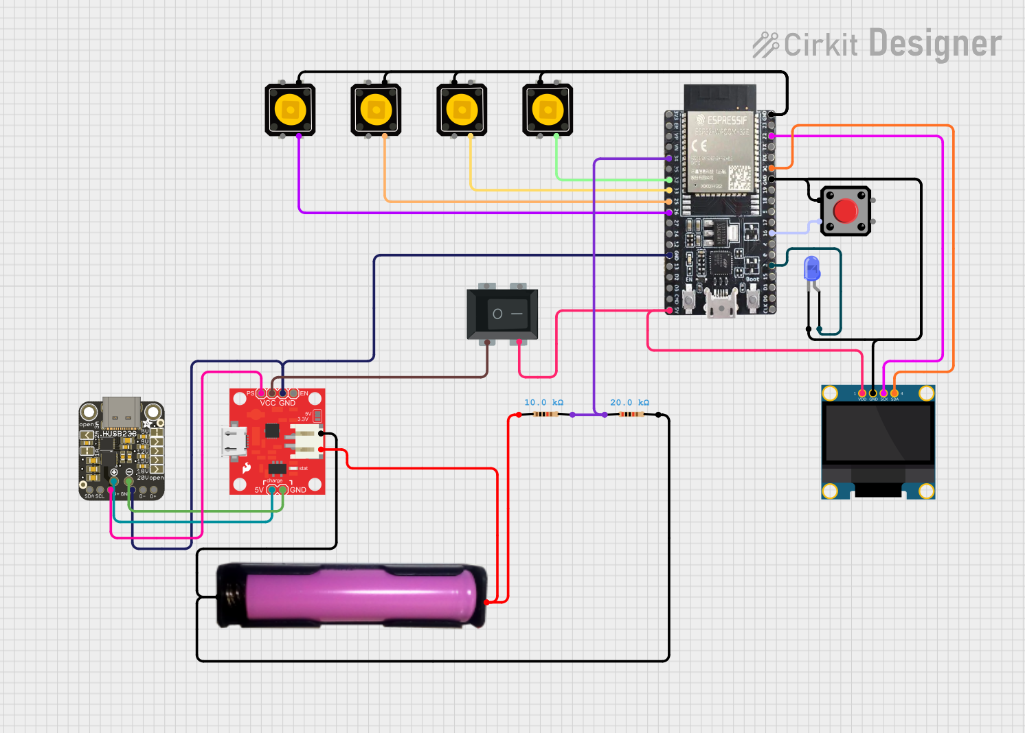

Explore Projects Built with stm32 bluepill
Common Applications and Use Cases
- Robotics and automation systems
- IoT devices and smart home applications
- Data acquisition and sensor interfacing
- Motor control and PWM-based applications
- Educational projects for learning ARM microcontrollers
Technical Specifications
The STM32 Blue Pill is equipped with the STM32F103C8T6 microcontroller and offers the following key specifications:
| Specification | Details |
|---|---|
| Microcontroller | STM32F103C8T6 |
| Architecture | ARM Cortex-M3 |
| Clock Speed | 72 MHz |
| Flash Memory | 64 KB (sometimes 128 KB depending on batch) |
| SRAM | 20 KB |
| Operating Voltage | 3.3V |
| Input Voltage Range | 5V (via USB) or 7-12V (via VIN pin) |
| GPIO Pins | 37 |
| Communication Interfaces | UART, SPI, I2C, CAN, USB |
| ADC Channels | 10 (12-bit resolution) |
| PWM Channels | 15 |
| Debugging Interface | SWD (Serial Wire Debug) |
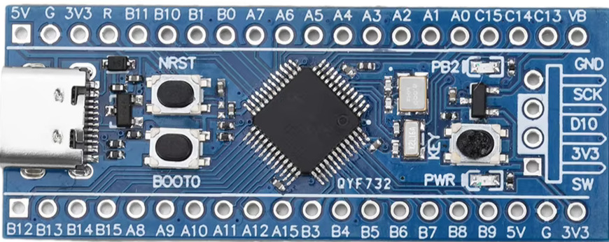
Pin Configuration and Descriptions
The STM32 Blue Pill has a 40-pin layout. Below is a summary of the pin configuration:
| Pin Name | Description |
|---|---|
| 3.3V | 3.3V output for powering peripherals |
| GND | Ground |
| VIN | Input voltage (7-12V) |
| PA0-PA15 | General-purpose I/O pins (Port A) |
| PB0-PB15 | General-purpose I/O pins (Port B) |
| PC13-PC15 | General-purpose I/O pins (Port C) |
| A0-A7 | Analog input pins |
| TX, RX | UART communication pins |
| SWDIO, SWCLK | Debugging interface pins |
| USB+ / USB- | USB data lines |
| NRST | Reset pin |
Usage Instructions
How to Use the STM32 Blue Pill in a Circuit
Powering the Board:
- Use the USB port for 5V input or connect an external power supply (7-12V) to the VIN pin.
- Ensure the board is properly grounded by connecting the GND pin.
Programming the Board:
- The STM32 Blue Pill can be programmed using the Arduino IDE, STM32CubeIDE, or PlatformIO.
- To upload code, connect the board to your computer via USB or use an external ST-Link programmer.
Connecting Peripherals:
- Use the GPIO pins for digital I/O operations.
- Connect sensors or analog devices to the ADC pins (A0-A7).
- For communication, use UART, SPI, or I2C pins as needed.
Setting the Boot Mode:
- The board has two boot mode pins: BOOT0 and BOOT1.
- To upload code via USB, set BOOT0 to 1 and BOOT1 to 0. After uploading, reset BOOT0 to 0.
Example Code for Arduino IDE
Below is an example of blinking an LED connected to pin PC13:
// Define the LED pin
#define LED_PIN PC13

void setup() {
  pinMode(LED_PIN, OUTPUT); // Set PC13 as an output pin
}

void loop() {
  digitalWrite(LED_PIN, HIGH); // Turn the LED on
  delay(500);                  // Wait for 500 milliseconds
  digitalWrite(LED_PIN, LOW);  // Turn the LED off
  delay(500);                  // Wait for 500 milliseconds
}
Important Considerations and Best Practices
- Voltage Levels: The STM32 Blue Pill operates at 3.3V logic levels. Ensure peripherals are compatible or use level shifters.
- Bootloader: Some boards may not come with a pre-installed bootloader. Use an ST-Link programmer to flash the bootloader if necessary.
- USB Connectivity: Install the correct USB drivers for your operating system to enable communication with the board.
Troubleshooting and FAQs
Common Issues and Solutions
The board is not recognized by the computer:
- Ensure the correct USB drivers are installed.
- Check the USB cable for faults or try a different cable.
Code upload fails:
- Verify the BOOT0 and BOOT1 pin settings.
- Ensure the correct board and port are selected in the programming environment.
The board does not power on:
- Check the power supply voltage and connections.
- Ensure the USB cable or external power source is functional.
Peripherals are not working as expected:
- Double-check the pin connections and configurations in the code.
- Verify that the peripherals are compatible with 3.3V logic levels.
FAQs
Q: Can I use the STM32 Blue Pill with the Arduino IDE?
A: Yes, the STM32 Blue Pill is compatible with the Arduino IDE. Install the STM32duino core to enable support.
Q: How do I reset the board?
A: Press the onboard reset button or toggle the NRST pin.
Q: What is the maximum current output of the 3.3V pin?
A: The 3.3V pin can supply up to 100 mA, depending on the power source.
Q: Can I use the STM32 Blue Pill for USB communication?
A: Yes, the board supports USB communication. Ensure the correct USB drivers are installed and configured.