How to Use XL 6009 STEP UP DC-DC: Examples, Pinouts, and Specs
Introduction
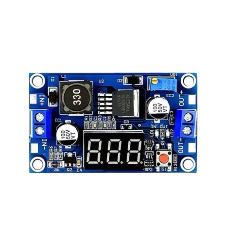
The XL6009 is a high-efficiency, step-up (boost) DC-DC converter module designed to increase an input voltage to a higher output voltage. It is based on the XL6009 regulator IC, which integrates a high-performance 400 kHz switching frequency and a wide input voltage range. This module is widely used in applications where a higher voltage is required from a lower voltage source, such as powering devices from batteries, solar panels, or USB power supplies.
Explore Projects Built with XL 6009 STEP UP DC-DC


Explore Projects Built with XL 6009 STEP UP DC-DC
Common Applications
- Powering devices requiring higher voltage from a low-voltage source
- Battery-powered systems
- Solar-powered projects
- LED drivers
- DIY electronics and Arduino projects
Technical Specifications
Key Technical Details
| Parameter | Value |
|---|---|
| Input Voltage Range | 3V to 32V |
| Output Voltage Range | 5V to 35V (adjustable via potentiometer) |
| Maximum Output Current | 4A (typical: 2A for stable operation) |
| Switching Frequency | 400 kHz |
| Efficiency | Up to 94% |
| Operating Temperature | -40°C to +85°C |
| Dimensions | ~43mm x 21mm x 14mm |
Pin Configuration and Descriptions
| Pin Name | Description |
|---|---|
| VIN | Input voltage pin. Connect the positive terminal of the input power source. |
| GND | Ground pin. Connect the negative terminal of the input power source. |
| VOUT | Output voltage pin. Provides the boosted voltage. |
Usage Instructions
How to Use the XL6009 in a Circuit
Connect the Input Voltage:
- Connect the positive terminal of your power source to the
VINpin. - Connect the negative terminal of your power source to the
GNDpin.
- Connect the positive terminal of your power source to the
Connect the Output Voltage:
- Connect the load (device to be powered) to the
VOUTpin. - Ensure the load's ground is connected to the
GNDpin.
- Connect the load (device to be powered) to the
Adjust the Output Voltage:
- Use the onboard potentiometer to adjust the output voltage.
- Turn the potentiometer clockwise to increase the output voltage and counterclockwise to decrease it.
- Use a multimeter to measure the output voltage while adjusting.
Verify Connections:
- Double-check all connections to ensure proper polarity and secure wiring.
Important Considerations
- Input Voltage Range: Ensure the input voltage is within the specified range (3V to 32V).
- Output Voltage Range: Do not exceed the maximum output voltage of 35V.
- Current Limitations: While the module can handle up to 4A, it is recommended to operate at 2A or below for stable performance.
- Heat Dissipation: At higher currents, the module may heat up. Consider adding a heatsink or active cooling if necessary.
- Polarity Protection: The module does not have built-in reverse polarity protection. Ensure correct polarity to avoid damage.
Example: Using XL6009 with Arduino UNO
The XL6009 can be used to power an Arduino UNO from a lower voltage source, such as a 3.7V Li-ion battery. Below is an example of how to connect the module:
- Connect the battery's positive terminal to the
VINpin and the negative terminal toGND. - Adjust the output voltage to 9V using the potentiometer.
- Connect the
VOUTpin to the Arduino's VIN pin and the module'sGNDto the Arduino's GND.
Sample Arduino Code
If you are using the XL6009 to power sensors or modules connected to the Arduino, here is an example code snippet to read a sensor value:
// Example code to read an analog sensor value and print it to the Serial Monitor

const int sensorPin = A0; // Analog pin connected to the sensor
int sensorValue = 0;      // Variable to store the sensor reading

void setup() {
  Serial.begin(9600); // Initialize serial communication at 9600 baud
}

void loop() {
  sensorValue = analogRead(sensorPin); // Read the sensor value
  Serial.print("Sensor Value: ");
  Serial.println(sensorValue); // Print the sensor value to the Serial Monitor
  delay(1000); // Wait for 1 second before the next reading
}
Note: Ensure the output voltage of the XL6009 is set to a level compatible with the Arduino and connected peripherals.
Troubleshooting and FAQs
Common Issues and Solutions
No Output Voltage:
- Check the input voltage and ensure it is within the specified range.
- Verify all connections, especially the polarity of the input and output.
Output Voltage Not Adjustable:
- Ensure the potentiometer is functioning correctly. If it is damaged, replace it.
- Verify that the input voltage is higher than the minimum required for the desired output.
Overheating:
- Reduce the load current to within the recommended range (2A or below).
- Add a heatsink or active cooling to the module.
Low Efficiency:
- Ensure the input voltage is not too close to the output voltage. The module operates more efficiently with a significant difference between input and output voltages.
Module Not Powering the Load:
- Check if the load requires more current than the module can provide.
- Verify that the output voltage is set correctly for the load.
FAQs
Q: Can the XL6009 step down voltage?
A: No, the XL6009 is a step-up (boost) converter and cannot step down voltage. For step-down applications, use a buck converter like the LM2596.
Q: Can I use the XL6009 with a solar panel?
A: Yes, the XL6009 can be used with a solar panel as long as the input voltage is within the specified range.
Q: Is the XL6009 suitable for audio applications?
A: The XL6009 may introduce noise due to its switching frequency, so it may not be ideal for sensitive audio applications without additional filtering.
Q: How do I protect the module from reverse polarity?
A: Use a diode or a reverse polarity protection circuit at the input to prevent damage.
By following this documentation, you can effectively use the XL6009 step-up DC-DC converter in your projects.