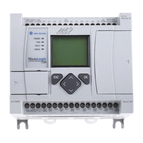
How to Use Micrologix 1100 PLC: Examples, Pinouts, and Specs
Introduction
The Micrologix 1100 PLC is a compact and versatile programmable logic controller (PLC) designed by Micrologix for small to medium automation applications. It combines built-in input/output (I/O) capabilities, communication ports, and advanced programming features, making it an ideal choice for industrial control systems, process automation, and machine control.
Explore Projects Built with Micrologix 1100 PLC


Explore Projects Built with Micrologix 1100 PLC
Common Applications and Use Cases
- Industrial automation and process control
- Machine control and monitoring
- Data acquisition and logging
- Remote monitoring and control via Ethernet
- Educational and training purposes for PLC programming
Technical Specifications
Key Technical Details
| Specification | Value |
|---|---|
| Manufacturer | Micrologix |
| Part ID | Micrologix 1100 |
| Power Supply Voltage | 24V DC or 120/240V AC |
| Digital Inputs | 10 (24V DC) |
| Digital Outputs | 6 (Relay) |
| Analog Inputs | 2 (10-bit resolution, 0-10V DC) |
| Communication Ports | Ethernet, RS-232/RS-485 Combo Port |
| Programming Software | RSLogix 500 |
| Memory | 4 KB User Program, 4 KB User Data |
| Expansion Capability | Up to 4 expansion I/O modules |
| Operating Temperature Range | 0°C to 55°C (32°F to 131°F) |
| Dimensions | 90 x 110 x 87 mm (H x W x D) |
Pin Configuration and Descriptions
Digital Inputs
| Pin Number | Description | Voltage Range | Notes |
|---|---|---|---|
| I:0/0 | Digital Input 0 | 24V DC | Sourcing or sinking input |
| I:0/1 | Digital Input 1 | 24V DC | Sourcing or sinking input |
| I:0/2 | Digital Input 2 | 24V DC | Sourcing or sinking input |
| I:0/3 | Digital Input 3 | 24V DC | Sourcing or sinking input |
| I:0/4 | Digital Input 4 | 24V DC | Sourcing or sinking input |
| I:0/5 | Digital Input 5 | 24V DC | Sourcing or sinking input |
| I:0/6 | Digital Input 6 | 24V DC | Sourcing or sinking input |
| I:0/7 | Digital Input 7 | 24V DC | Sourcing or sinking input |
| I:0/8 | Digital Input 8 | 24V DC | Sourcing or sinking input |
| I:0/9 | Digital Input 9 | 24V DC | Sourcing or sinking input |
Digital Outputs
| Pin Number | Description | Type | Voltage/Current Rating |
|---|---|---|---|
| O:0/0 | Digital Output 0 | Relay | 240V AC/2A or 30V DC/2A |
| O:0/1 | Digital Output 1 | Relay | 240V AC/2A or 30V DC/2A |
| O:0/2 | Digital Output 2 | Relay | 240V AC/2A or 30V DC/2A |
| O:0/3 | Digital Output 3 | Relay | 240V AC/2A or 30V DC/2A |
| O:0/4 | Digital Output 4 | Relay | 240V AC/2A or 30V DC/2A |
| O:0/5 | Digital Output 5 | Relay | 240V AC/2A or 30V DC/2A |
Analog Inputs
| Pin Number | Description | Voltage Range | Resolution |
|---|---|---|---|
| AI:0/0 | Analog Input 0 | 0-10V DC | 10-bit |
| AI:0/1 | Analog Input 1 | 0-10V DC | 10-bit |
Usage Instructions
How to Use the Micrologix 1100 in a Circuit
Power Supply Connection:
- Connect a 24V DC or 120/240V AC power supply to the PLC's power terminals.
- Ensure proper grounding to avoid electrical noise or damage.
Input Connections:
- Connect digital input devices (e.g., push buttons, sensors) to the input terminals.
- For analog inputs, connect devices providing 0-10V DC signals (e.g., potentiometers, transducers).
Output Connections:
- Connect output devices (e.g., relays, solenoids, indicator lights) to the output terminals.
- Ensure the connected devices do not exceed the rated voltage/current.
Communication Setup:
- Use the Ethernet port for network communication or remote monitoring.
- Use the RS-232/RS-485 combo port for serial communication with other devices.
Programming:
- Install RSLogix 500 software on your computer.
- Connect the PLC to your computer via Ethernet or serial cable.
- Create and download your ladder logic program to the PLC.
Important Considerations and Best Practices
- Always verify the power supply voltage before connecting to the PLC.
- Use proper shielding and grounding for analog input signals to minimize noise.
- Avoid exceeding the maximum current ratings for digital outputs to prevent damage.
- Regularly back up your PLC program to avoid data loss.
- Follow safety guidelines when working with high-voltage devices connected to the PLC.
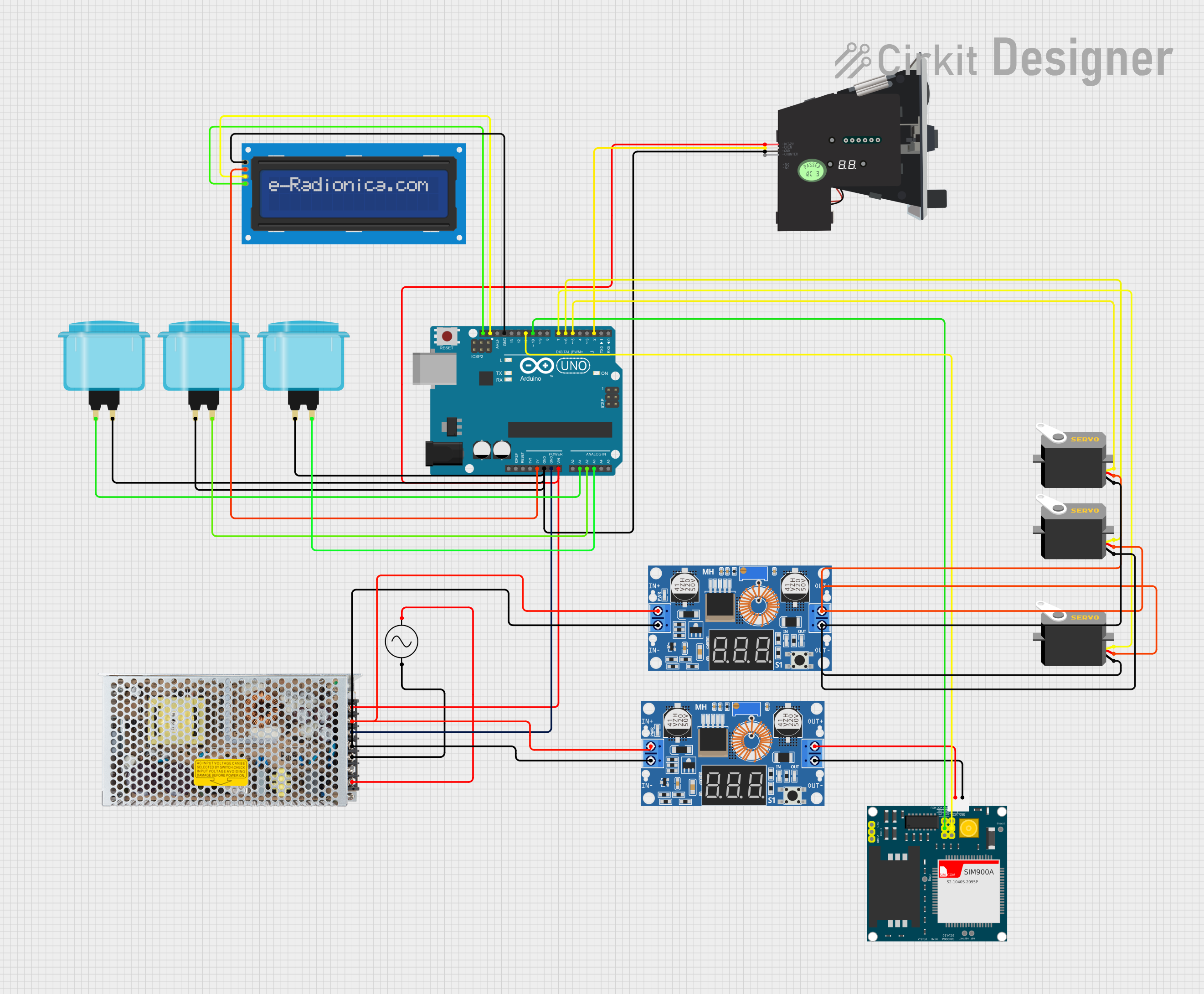
Example Code for Arduino UNO Communication
The Micrologix 1100 can communicate with an Arduino UNO via RS-232. Below is an example of Arduino code to send data to the PLC:
#include <SoftwareSerial.h>

// Define RX and TX pins for SoftwareSerial
SoftwareSerial plcSerial(10, 11); // RX = pin 10, TX = pin 11

void setup() {
  // Start serial communication with the PLC
  plcSerial.begin(9600); // Set baud rate to match PLC settings
  Serial.begin(9600);    // For debugging on the Serial Monitor

  Serial.println("Arduino to Micrologix 1100 Communication Started");
}

void loop() {
  // Example: Send a command to the PLC
  String command = "DATA:123"; // Replace with actual PLC command
  plcSerial.println(command);  // Send command to PLC

  // Check for response from the PLC
  if (plcSerial.available()) {
    String response = plcSerial.readString();
    Serial.println("PLC Response: " + response); // Print response to Serial Monitor
  }

  delay(1000); // Wait 1 second before sending the next command
}
Note: Ensure the RS-232 to TTL converter is used to interface the Arduino with the PLC.
Troubleshooting and FAQs
Common Issues and Solutions
PLC Not Powering On:
- Verify the power supply voltage and connections.
- Check for blown fuses or tripped circuit breakers.
Inputs Not Responding:
- Ensure the input devices are properly connected and powered.
- Check the input wiring for loose connections or damage.
Outputs Not Activating:
- Verify the output devices are within the rated voltage/current limits.
- Check the ladder logic program for errors or missing output instructions.
Communication Failure:
- Ensure the correct communication settings (baud rate, parity, etc.) are configured.
- Check the Ethernet or serial cable connections.
FAQs
Q: Can the Micrologix 1100 be programmed wirelessly?
A: No, the Micrologix 1100 does not support wireless programming. Use Ethernet or serial communication for programming.
Q: What is the maximum expansion capability of the Micrologix 1100?
A: The PLC supports up to 4 expansion I/O modules.
Q: Can I use third-party software to program the Micrologix 1100?
A: No, the Micrologix 1100 is programmed exclusively using RSLogix 500 software.
Q: How do I reset the PLC to factory settings?
A: Use the RSLogix 500 software to clear the program and reset the PLC to its default state.
Q: Is the Micrologix 1100 suitable for high-speed applications?
A: The Micrologix 1100 is designed for small to medium automation tasks and may not be suitable for high-speed or time-critical applications.