
How to Use Transformer 3 - 12v: Examples, Pinouts, and Specs
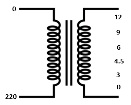
 Design with Transformer 3 - 12v in Cirkit Designer
Introduction
The Transformer 3 - 12v is a step-down transformer designed to reduce a higher input voltage to a stable 12V output. This component is widely used in power supply circuits to provide the necessary voltage for various electronic devices, such as microcontrollers, sensors, and small appliances. Its robust design ensures reliable performance in both hobbyist and industrial applications.
Explore Projects Built with Transformer 3 - 12v
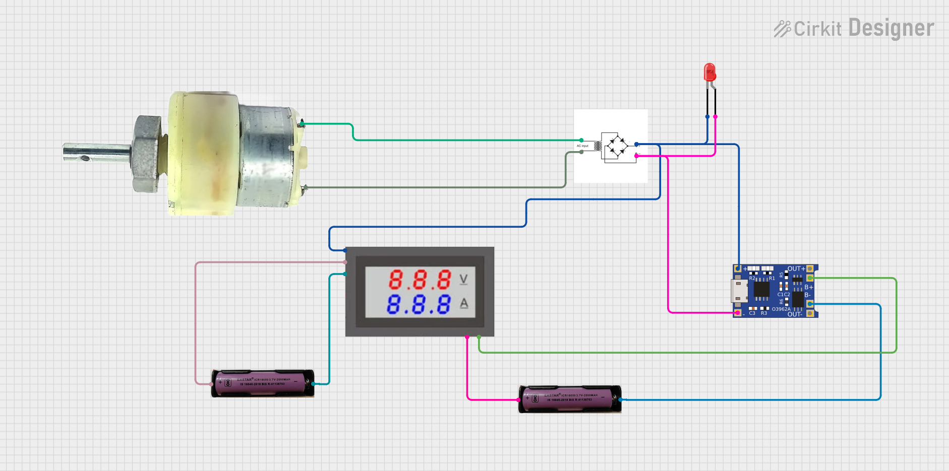 Open Project in Cirkit Designer
 Open Project in Cirkit Designer
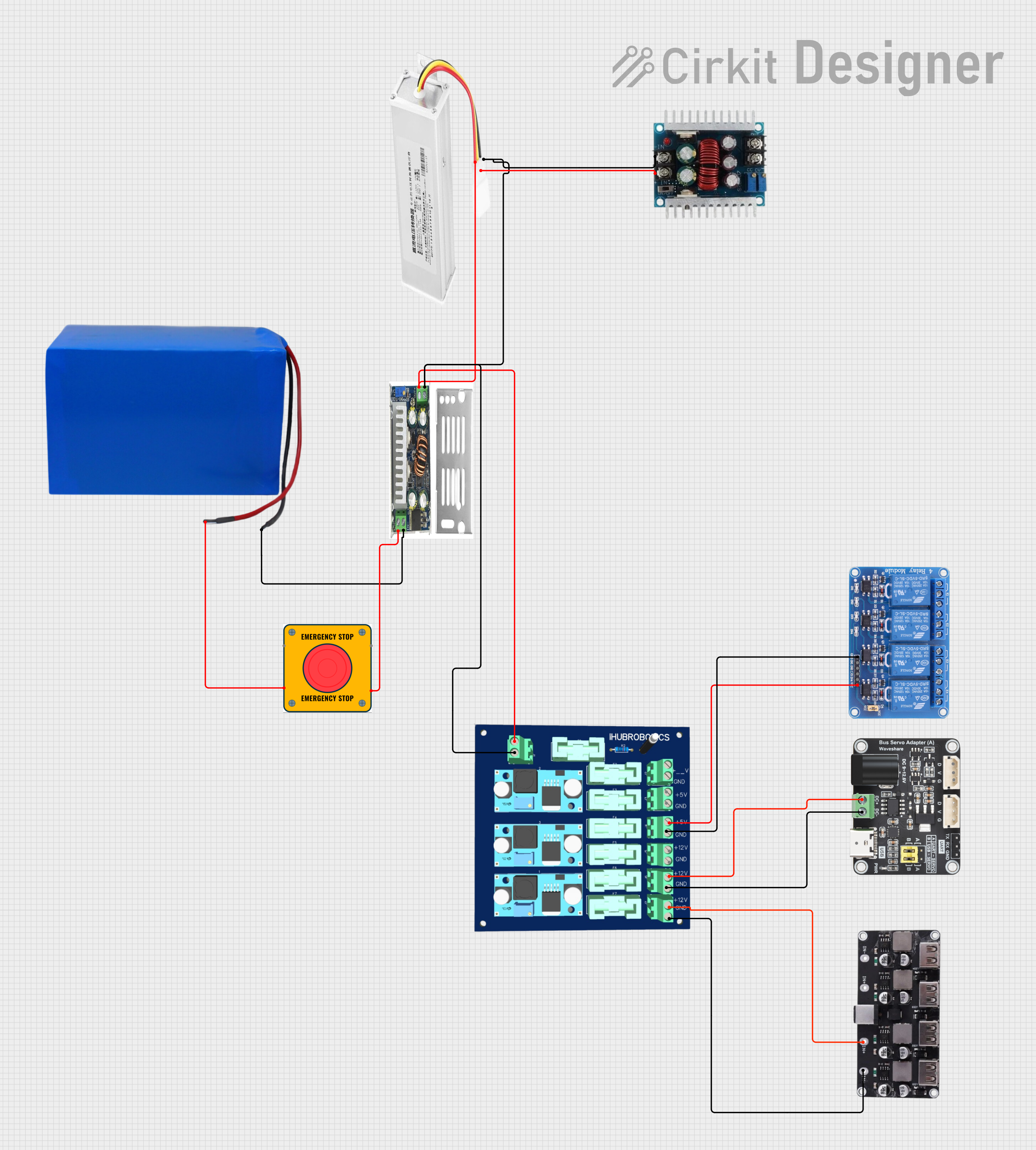 Open Project in Cirkit Designer
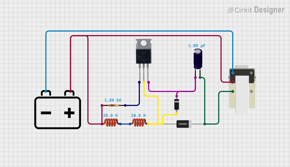 Open Project in Cirkit Designer
Explore Projects Built with Transformer 3 - 12v
Open Project in Cirkit DesignerOpen Project in Cirkit DesignerOpen Project in Cirkit DesignerOpen Project in Cirkit DesignerCommon Applications:
- Power supply units for electronic devices
- Voltage regulation in circuits
- Low-voltage lighting systems
- Battery charging circuits
- Industrial control systems
Technical Specifications
Below are the key technical details for the Transformer 3 - 12v:
| Parameter | Value |
|---|---|
| Manufacturer | Transformer 3 - 12v |
| Part ID | Transformer 3 - 12v |
| Input Voltage Range | 110V - 240V AC |
| Output Voltage | 12V AC |
| Output Current | 1A (typical), 2A (maximum) |
| Frequency | 50Hz / 60Hz |
| Efficiency | ≥ 85% |
| Insulation Resistance | ≥ 100MΩ |
| Operating Temperature | -10°C to +50°C |
| Dimensions | 50mm x 40mm x 35mm |
| Weight | 200g |
Pin Configuration and Descriptions
The Transformer 3 - 12v has four terminals, as described below:
| Pin | Label | Description |
|---|---|---|
| 1 | Primary Input 1 | Connect to the live (L) wire of the AC mains input. |
| 2 | Primary Input 2 | Connect to the neutral (N) wire of the AC mains input. |
| 3 | Secondary Output 1 | Provides one side of the 12V AC output. |
| 4 | Secondary Output 2 | Provides the other side of the 12V AC output (completes the circuit). |
Note: Ensure proper insulation and safety precautions when working with AC mains voltage.
Usage Instructions
How to Use the Transformer in a Circuit
Connect the Primary Side:
- Identify the primary input terminals (Pin 1 and Pin 2).
- Connect Pin 1 to the live (L) wire and Pin 2 to the neutral (N) wire of the AC mains supply.
- Use a fuse or circuit breaker for safety.
Connect the Secondary Side:
- Identify the secondary output terminals (Pin 3 and Pin 4).
- Connect these terminals to the load or rectifier circuit to step down the voltage to 12V AC.
Rectification (Optional):
- If DC voltage is required, use a bridge rectifier and a smoothing capacitor to convert the 12V AC output to 12V DC.
Testing:
- Use a multimeter to verify the output voltage before connecting sensitive devices.
Important Considerations and Best Practices
- Safety First: Always disconnect the transformer from the mains supply before making any connections or modifications.
- Load Matching: Ensure the connected load does not exceed the transformer's maximum current rating (2A).
- Heat Dissipation: Allow adequate ventilation around the transformer to prevent overheating.
- Grounding: Properly ground the transformer to avoid electrical hazards.
- Isolation: Use insulating materials to prevent accidental contact with live terminals.
Example: Using with an Arduino UNO
To power an Arduino UNO, the transformer's 12V AC output must first be converted to DC. Below is an example circuit and code:
Circuit:
- Connect the transformer's secondary output to a bridge rectifier.
- Add a 1000µF capacitor across the rectifier's DC output to smooth the voltage.
- Use a 7805 voltage regulator to step down the DC voltage to 5V for the Arduino UNO.
Code:
// Example Arduino code to blink an LED using power from Transformer 3 - 12v
// Ensure the transformer output is properly rectified and regulated to 5V DC.

const int ledPin = 13; // Pin connected to the onboard LED

void setup() {
  pinMode(ledPin, OUTPUT); // Set the LED pin as an output
}

void loop() {
  digitalWrite(ledPin, HIGH); // Turn the LED on
  delay(1000);               // Wait for 1 second
  digitalWrite(ledPin, LOW);  // Turn the LED off
  delay(1000);               // Wait for 1 second
}
Note: Ensure the Arduino UNO is powered via its 5V input pin or USB port after proper voltage regulation.
Troubleshooting and FAQs
Common Issues and Solutions
| Issue | Possible Cause | Solution |
|---|---|---|
| No output voltage | Incorrect wiring on the primary side | Verify the connections to the AC mains input. |
| Output voltage too low or unstable | Overloaded transformer | Reduce the load to within the transformer's rated current capacity. |
| Transformer overheating | Prolonged overcurrent or poor ventilation | Ensure the load is within limits and provide adequate airflow around the unit. |
| Buzzing noise | Loose laminations or high inrush current | Tighten the transformer mounting or use an inrush current limiter. |
FAQs
Can this transformer be used with DC input?
- No, the transformer is designed for AC input only. Using DC input will damage the component.
What happens if I exceed the maximum current rating?
- Exceeding the current rating may cause overheating, reduced efficiency, or permanent damage to the transformer.
Can I use this transformer outdoors?
- The transformer is not weatherproof. Use it indoors or in a properly enclosed environment.
How do I know if the transformer is working correctly?
- Measure the output voltage with a multimeter. It should read approximately 12V AC under no-load conditions.
By following this documentation, you can safely and effectively use the Transformer 3 - 12v in your electronic projects.