How to Use TB6600: Examples, Pinouts, and Specs
Introduction
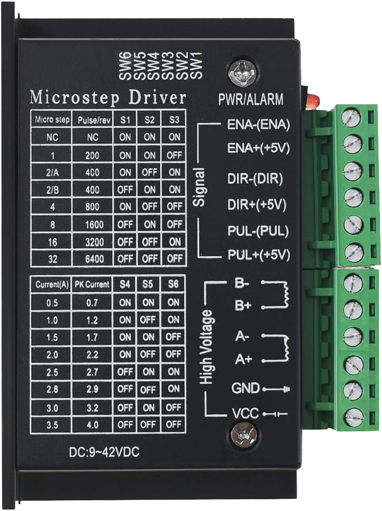
The TB6600 Stepper Motor Driver is a professional two-phase stepper motor driver compatible with a wide range of stepper motors. Manufactured by DFROBOT, the TB6600 is designed to drive bipolar stepper motors in various applications, including CNC machines, engraving machines, robotics, and precision control systems. Its ability to adjust current output and microstep resolution makes it a versatile choice for projects requiring precise motor control.
Explore Projects Built with TB6600


Explore Projects Built with TB6600
Common Applications and Use Cases
- CNC machines
- 3D printers
- Laser cutters
- Robotic arms
- Precision positioning systems
Technical Specifications
Key Technical Details
- Supply Voltage: 9V to 42V DC
- Output Current: Adjustable from 0.5A to 4.0A (peak)
- Input Signal Voltage: 3.3V to 24V
- Microstep Resolutions: Full, 1/2, 1/4, 1/8, 1/16
- Operating Temperature: -10°C to 45°C
- Dimensions: 96mm x 71mm x 28mm
Pin Configuration and Descriptions
| Pin Number | Pin Name | Description |
|---|---|---|
| 1 | ENA+ | Enable signal positive input |
| 2 | ENA- | Enable signal negative input |
| 3 | DIR+ | Direction signal positive input |
| 4 | DIR- | Direction signal negative input |
| 5 | PUL+ | Pulse signal positive input |
| 6 | PUL- | Pulse signal negative input |
| 7 | A+ | Motor phase A positive output |
| 8 | A- | Motor phase A negative output |
| 9 | B+ | Motor phase B positive output |
| 10 | B- | Motor phase B negative output |
| 11 | VCC | Power supply positive input |
| 12 | GND | Power supply ground |
Usage Instructions
How to Use the Component in a Circuit
Power Supply Connection: Connect a DC power supply to the VCC and GND pins, ensuring the voltage is within the specified range (9V to 42V).
Motor Connection: Connect the stepper motor wires to the A+/- and B+/- output terminals, matching the motor's phase wires.
Control Signal Connection: Connect the PUL+, PUL-, DIR+, and DIR- to the corresponding control signals from your microcontroller or control board. The ENA+/- can be used to enable or disable the driver.
Microstep Setting: Adjust the microstep resolution by setting the appropriate DIP switches on the driver according to the desired steps per revolution.
Current Setting: Set the current limit using the onboard potentiometer to match the requirements of your stepper motor.
Important Considerations and Best Practices
- Always ensure the power supply is turned off before making any connections to prevent damage.
- Use a suitable heat sink to dissipate heat during operation.
- Avoid running the motor driver at its maximum current for extended periods to prevent overheating.
- Ensure that the control signals are compatible with the voltage levels of the TB6600.
Troubleshooting and FAQs
Common Issues Users Might Face
- Motor not moving: Check connections, ensure the power supply is adequate, and verify that the control signals are being sent correctly.
- Overheating: Ensure proper heat dissipation and check if the current settings are too high for the motor.
- Inconsistent movement: Verify microstep settings and adjust current limit if necessary.
Solutions and Tips for Troubleshooting
- Double-check wiring and connections for any loose or incorrect connections.
- Use a multimeter to verify the voltage levels at the power supply and control signal inputs.
- Reduce the current setting if the driver or motor becomes too hot to touch.
- Consult the motor's datasheet to ensure the current and microstep settings are within its specifications.
Example Code for Arduino UNO
// Define the connections to the Arduino
const int dirPin = 2; // DIR+ to digital pin 2
const int stepPin = 3; // PUL+ to digital pin 3
const int enablePin = 8; // ENA+ to digital pin 8

void setup() {
  // Set the pin modes
  pinMode(stepPin, OUTPUT);
  pinMode(dirPin, OUTPUT);
  pinMode(enablePin, OUTPUT);

  // Enable the motor driver
  digitalWrite(enablePin, LOW);
}

void loop() {
  // Set the direction
  digitalWrite(dirPin, HIGH); // Set to LOW to change direction

  // Move the motor with a simple square wave
  for (int i = 0; i < 200; i++) {
    // Generate a pulse
    digitalWrite(stepPin, HIGH);
    delayMicroseconds(500); // This delay controls the speed
    digitalWrite(stepPin, LOW);
    delayMicroseconds(500); // This delay controls the speed
  }

  // Wait before changing direction
  delay(1000);

  // Change direction
  digitalWrite(dirPin, LOW);

  // Move the motor in the opposite direction
  for (int i = 0; i < 200; i++) {
    // Generate a pulse
    digitalWrite(stepPin, HIGH);
    delayMicroseconds(500); // Adjust the speed as needed
    digitalWrite(stepPin, LOW);
    delayMicroseconds(500); // Adjust the speed as needed
  }

  // Wait before the next move
  delay(1000);
}
Note: The above code is a simple example to demonstrate the basic operation of the TB6600 with an Arduino UNO. Adjust the delayMicroseconds value to control the speed of the stepper motor. The for loop iteration count controls the number of steps the motor will take. Ensure that the TB6600's current settings are configured correctly for your specific stepper motor.