How to Use Electrolytic Capacitor: Examples, Pinouts, and Specs
Introduction
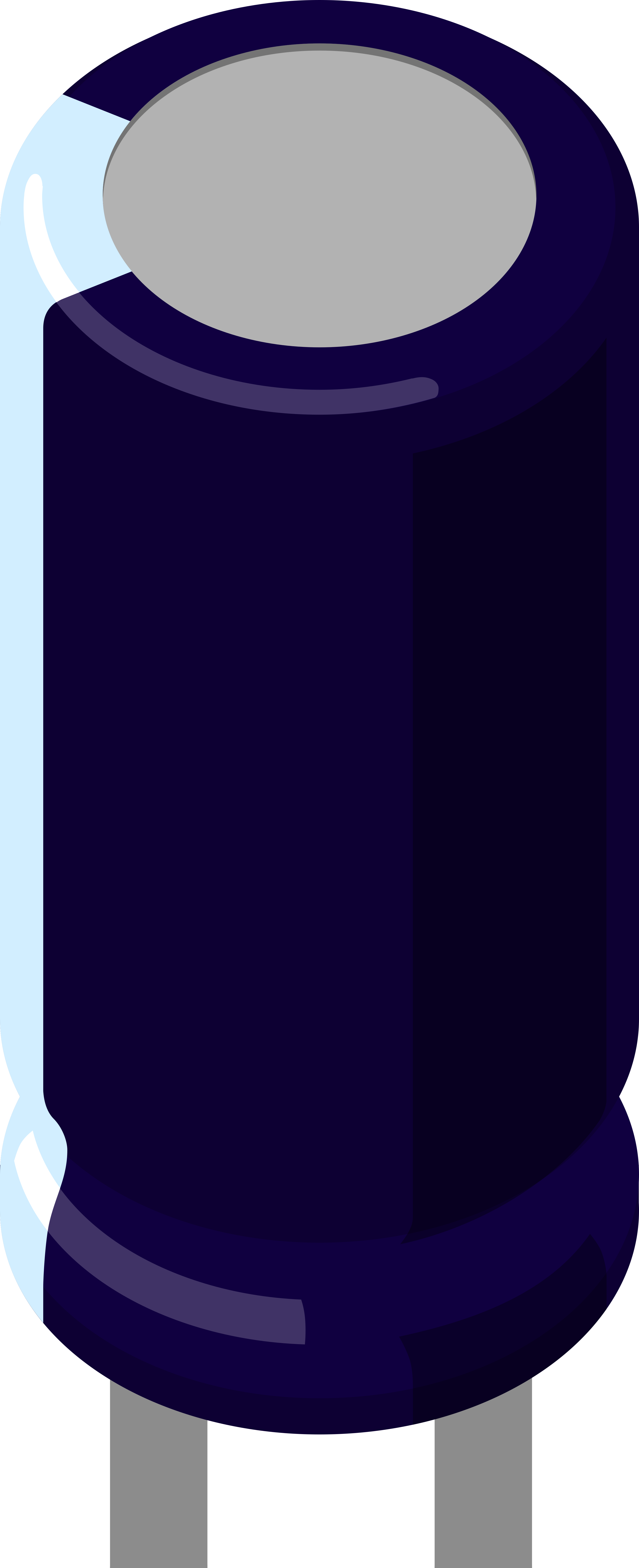
An electrolytic capacitor is a polarized capacitor which uses an electrolyte (an ionic conducting liquid) as one of its plates to achieve a larger capacitance per unit volume than other types of capacitors. This makes them valuable in relatively high-current and low-frequency electrical circuits, particularly in power supply filtering and audio signal processing.
Explore Projects Built with Electrolytic Capacitor
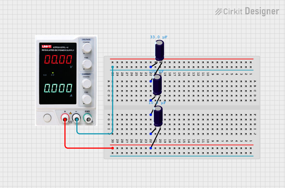

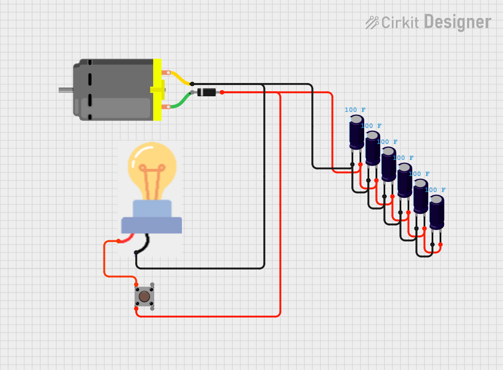

Explore Projects Built with Electrolytic Capacitor
Common Applications and Use Cases
- Smoothing the output of power supplies
- Coupling and decoupling in audio amplifiers and power amplifiers
- Timing circuits
- Energy storage in pulsed systems
- Frequency tuning in radio transmitters and receivers
Technical Specifications
Key Technical Details
- Capacitance Range: Typically from 1 µF to 47,000 µF
- Voltage Rating: Usually from 6.3V to 450V (or higher for specialized applications)
- Tolerance: Commonly ±20%
- Temperature Range: Varies with type, but often -40°C to +105°C
- Leakage Current: Depends on size, age, temperature, and voltage rating
- Equivalent Series Resistance (ESR): Varies with frequency and temperature
Pin Configuration and Descriptions
| Pin Number | Description |
|---|---|
| 1 | Anode (+) |
| 2 | Cathode (-) |
Note: The anode is typically marked with a plus sign and the cathode with a minus sign or a stripe on the casing.
Usage Instructions
How to Use the Component in a Circuit
- Polarity: Ensure the correct polarity when connecting an electrolytic capacitor in a circuit. The positive terminal (anode) must connect to the higher potential, and the negative terminal (cathode) to the lower potential.
- Voltage Rating: Do not exceed the voltage rating of the capacitor, as this can lead to failure or even explosion.
- Temperature: Operate within the specified temperature range to ensure longevity and reliability.
- Mounting: When mounting, ensure adequate spacing and ventilation to prevent overheating.
Important Considerations and Best Practices
- Pre-Charging: In high-current applications, consider pre-charging the capacitor to prevent inrush current damage.
- Decoupling: Use decoupling capacitors close to power pins of integrated circuits to filter out noise.
- Lifetime: Be aware that electrolytic capacitors have a limited lifetime and may need to be replaced after several years, especially in high-temperature applications.
Troubleshooting and FAQs
Common Issues
- Bulging or Leaking: If the capacitor is bulging or leaking, it has failed and must be replaced.
- Noisy Circuit: A noisy circuit can sometimes be caused by a capacitor with high ESR. Replace the capacitor if this is suspected.
- Circuit Not Working: If the circuit is not working and the capacitor is in a critical path, check if it is installed with the correct polarity or if it has failed open or short.
Solutions and Tips for Troubleshooting
- Polarity Check: Always double-check the polarity before powering up the circuit.
- Voltage Rating: Use a capacitor with a voltage rating higher than the circuit's maximum voltage to provide a safety margin.
- Replacement: When replacing, ensure the new capacitor matches the capacitance and voltage ratings of the original.
FAQs
Q: Can I replace an electrolytic capacitor with one of a higher voltage rating?
A: Yes, as long as the capacitance is the same and the physical size is compatible with your circuit.
Q: What happens if I reverse the polarity of an electrolytic capacitor?
A: Reversing the polarity can cause the capacitor to fail, potentially resulting in leakage, overheating, or explosion.
Q: How do I dispose of a failed electrolytic capacitor?
A: Follow local regulations for the disposal of electronic components, as capacitors may contain hazardous materials.
Q: Can I use an electrolytic capacitor in a high-frequency circuit?
A: Electrolytic capacitors are not ideal for high-frequency applications due to their relatively high ESR and inductance. Consider using ceramic or film capacitors for high-frequency circuits.
Example Arduino Connection (Optional)
Electrolytic capacitors are not typically interfaced with microcontrollers like the Arduino directly, but they are used to smooth out the power supply that feeds the Arduino and its peripherals. Below is an example of how to connect an electrolytic capacitor to an Arduino UNO for power supply smoothing:
// No specific code is required for the capacitor itself, as it is a passive component.
// However, here is an example of how to connect it to an Arduino UNO:

// Connect the anode of the capacitor to the 5V output of the Arduino.
// Connect the cathode of the capacitor to the GND.

// The capacitor will act to smooth out any voltage spikes or drops, providing a more stable
// power supply to the Arduino and any connected components.
Note: This is a conceptual representation and not an actual code snippet, as passive components like capacitors do not require code to function.