
How to Use SO14: Examples, Pinouts, and Specs
 Design with SO14 in Cirkit Designer
Introduction
The SO14 is a small outline integrated circuit (SOIC) package with 14 pins, designed for surface-mount technology (SMT). Its compact size and efficient heat dissipation make it ideal for applications where space is limited and thermal management is critical. The SO14 package is widely used in consumer electronics, automotive systems, industrial equipment, and communication devices. It is commonly employed to house integrated circuits such as operational amplifiers, microcontrollers, and logic gates.
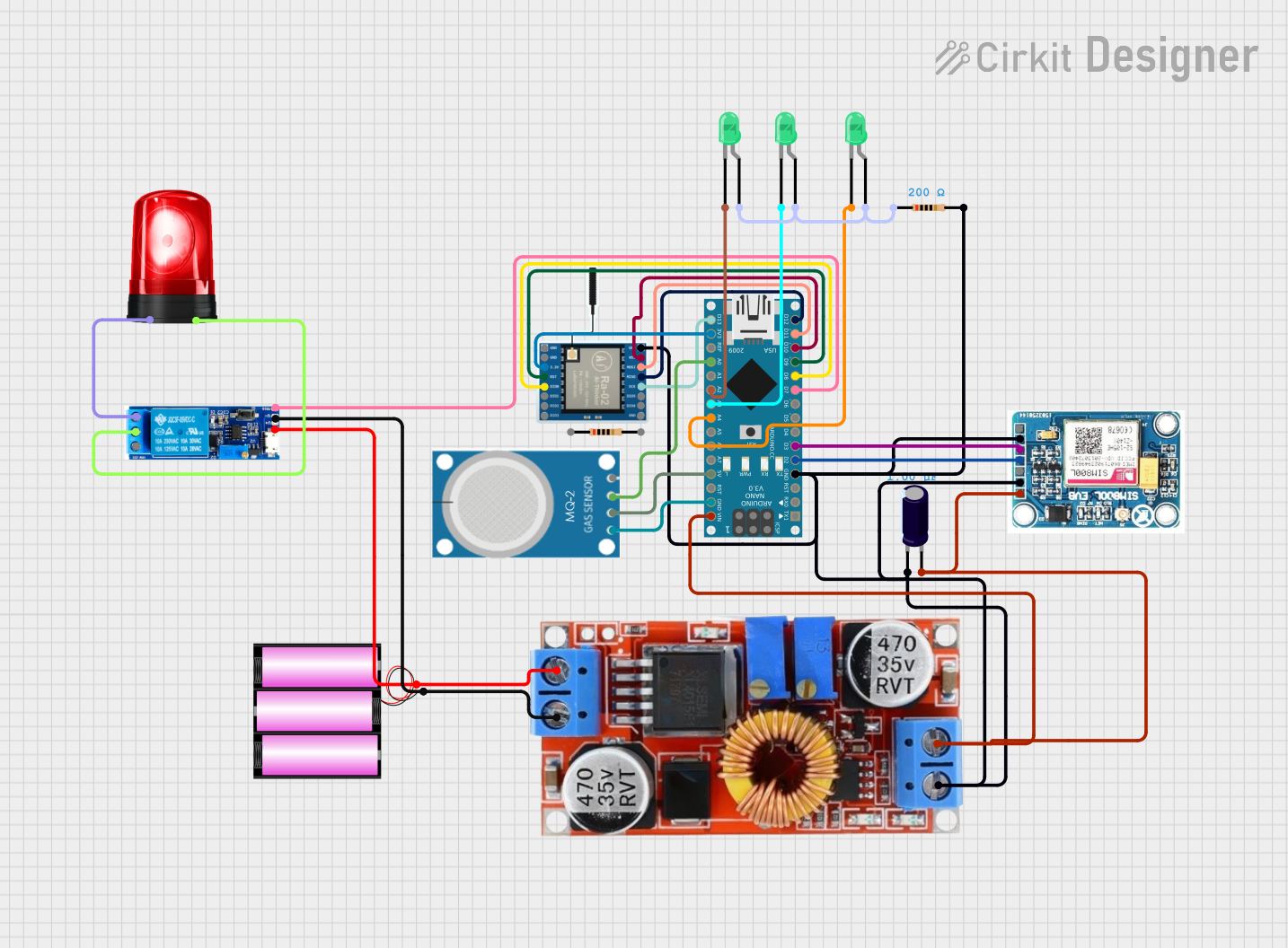
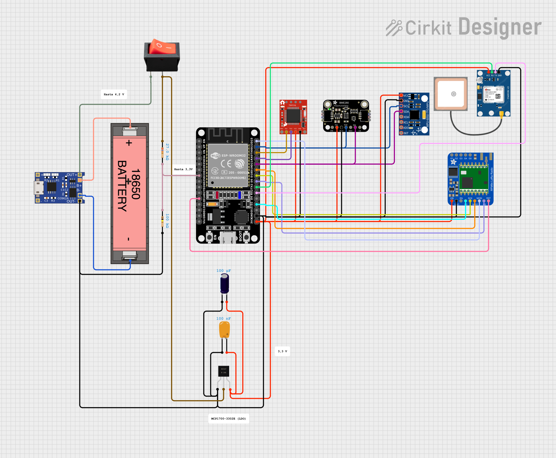
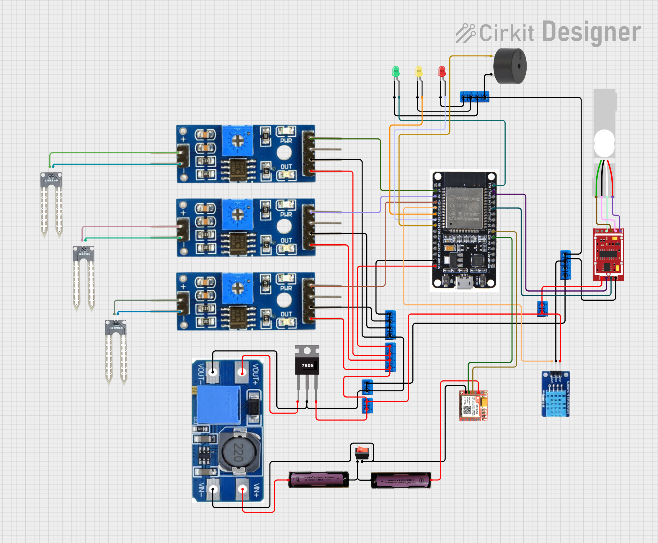
Explore Projects Built with SO14
 Open Project in Cirkit Designer
 Open Project in Cirkit Designer
 Open Project in Cirkit Designer
 Open Project in Cirkit Designer
Explore Projects Built with SO14
Open Project in Cirkit DesignerOpen Project in Cirkit DesignerOpen Project in Cirkit DesignerOpen Project in Cirkit DesignerCommon Applications:
- Consumer electronics (e.g., TVs, smartphones, and audio devices)
- Automotive systems (e.g., engine control units and sensors)
- Industrial automation and control systems
- Communication devices (e.g., modems and transceivers)
Technical Specifications
The SO14 package is defined by its physical and electrical characteristics, which are critical for proper integration into circuits.
Key Technical Details:
- Number of Pins: 14
- Package Type: Small Outline Integrated Circuit (SOIC)
- Pin Pitch: 1.27 mm (distance between adjacent pins)
- Body Width: 3.9 mm to 4.0 mm
- Body Length: 8.55 mm to 8.75 mm
- Maximum Height: 1.75 mm
- Thermal Resistance (Junction-to-Ambient): Typically 100°C/W (varies by IC housed)
- Mounting Type: Surface-mount technology (SMT)
- Material: Plastic encapsulation with metal leads
Pin Configuration and Descriptions:
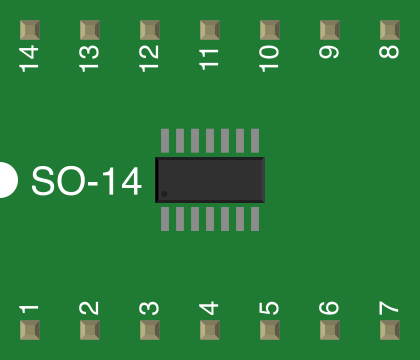
The SO14 package has 14 pins arranged in two parallel rows. The pinout and functionality depend on the specific integrated circuit housed within the package. Below is a generic pin configuration for reference:
| Pin Number | Description | Notes |
|---|---|---|
| 1 | Input/Output (I/O) or VCC | Function depends on IC design |
| 2 | Input/Output (I/O) | |
| 3 | Input/Output (I/O) | |
| 4 | Input/Output (I/O) | |
| 5 | Input/Output (I/O) | |
| 6 | Input/Output (I/O) | |
| 7 | Ground (GND) | Common ground connection |
| 8 | Input/Output (I/O) | |
| 9 | Input/Output (I/O) | |
| 10 | Input/Output (I/O) | |
| 11 | Input/Output (I/O) | |
| 12 | Input/Output (I/O) | |
| 13 | Input/Output (I/O) | |
| 14 | Input/Output (I/O) or VCC | Function depends on IC design |
Note: Always refer to the datasheet of the specific IC housed in the SO14 package for exact pin functionality.
Usage Instructions
How to Use the SO14 in a Circuit:
Soldering:
- Use a reflow soldering process for SMT assembly. Ensure the PCB footprint matches the SO14 dimensions.
- Apply solder paste to the PCB pads and align the SO14 package carefully.
- Heat the assembly to the recommended reflow temperature profile (typically 240–260°C peak).
Power Supply:
- Ensure the power supply voltage matches the requirements of the IC housed in the SO14 package.
- Connect the VCC and GND pins to the appropriate power and ground rails.
Signal Connections:
- Connect the input/output pins to the corresponding circuit components as per the IC's datasheet.
- Use decoupling capacitors near the power pins to reduce noise and improve stability.
Thermal Management:
- Ensure adequate ventilation or heat sinking if the IC generates significant heat during operation.
Important Considerations:
- PCB Design: Ensure the PCB layout adheres to the SO14 footprint and includes proper trace widths for current handling.
- Static Sensitivity: Handle the SO14 package with care to avoid electrostatic discharge (ESD) damage.
- IC-Specific Requirements: Always consult the datasheet of the IC housed in the SO14 package for detailed electrical and functional specifications.
Example: Connecting an SO14 IC to an Arduino UNO
If the SO14 package contains a digital IC (e.g., a shift register), it can be interfaced with an Arduino UNO. Below is an example of Arduino code to control a shift register housed in an SO14 package:
// Example: Controlling a shift register in an SO14 package with Arduino UNO
// This example assumes the shift register is a 74HC595 IC.

const int dataPin = 11;   // Pin connected to DS (Serial Data Input)
const int clockPin = 13;  // Pin connected to SHCP (Shift Clock)
const int latchPin = 10;  // Pin connected to STCP (Storage Register Clock)

void setup() {
  pinMode(dataPin, OUTPUT);  // Set data pin as output
  pinMode(clockPin, OUTPUT); // Set clock pin as output
  pinMode(latchPin, OUTPUT); // Set latch pin as output
}

void loop() {
  digitalWrite(latchPin, LOW); // Prepare to send data
  shiftOut(dataPin, clockPin, MSBFIRST, 0b10101010);
  // Send data to shift register (example pattern: 10101010)
  digitalWrite(latchPin, HIGH); // Latch the data to output pins
  delay(1000); // Wait for 1 second

  digitalWrite(latchPin, LOW); // Prepare to send new data
  shiftOut(dataPin, clockPin, MSBFIRST, 0b01010101);
  // Send new data to shift register (example pattern: 01010101)
  digitalWrite(latchPin, HIGH); // Latch the data to output pins
  delay(1000); // Wait for 1 second
}
Note: The pin connections and code will vary depending on the specific IC housed in the SO14 package. Always refer to the IC's datasheet for accurate details.
Troubleshooting and FAQs
Common Issues:
Incorrect Soldering:
- Issue: Pins are bridged or not properly soldered.
- Solution: Inspect the solder joints under a magnifying glass and rework as needed.
Overheating During Soldering:
- Issue: Excessive heat damages the IC or package.
- Solution: Use a controlled soldering process and avoid prolonged exposure to high temperatures.
Incorrect Pin Connections:
- Issue: Pins are connected to the wrong signals or power rails.
- Solution: Double-check the pinout and circuit connections against the IC's datasheet.
ESD Damage:
- Issue: The IC is damaged due to electrostatic discharge.
- Solution: Use proper ESD precautions, such as grounding straps and anti-static mats.
FAQs:
Q: Can the SO14 package be used in high-temperature environments?
A: The SO14 package can typically operate up to 125°C, but always check the IC's datasheet for specific temperature ratings.Q: How do I identify pin 1 on the SO14 package?
A: Pin 1 is marked with a dot or notch on the package. Align this mark with the corresponding pin 1 location on the PCB.Q: Can I use the SO14 package for through-hole mounting?
A: No, the SO14 package is designed specifically for surface-mount technology (SMT).
By following this documentation, users can effectively integrate and troubleshoot the SO14 package in their electronic designs.