
How to Use DC motor: Examples, Pinouts, and Specs
 Design with DC motor in Cirkit Designer
Introduction
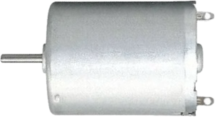
A DC motor is an electromechanical device that converts direct current (DC) electrical energy into mechanical energy, enabling rotational motion. It operates based on the principle of electromagnetic induction, where a magnetic field interacts with current-carrying conductors to produce torque. DC motors are widely used in applications such as robotics, fans, conveyor belts, and electric vehicles due to their simplicity, reliability, and ease of control.
Explore Projects Built with DC motor
 Open Project in Cirkit Designer
 Open Project in Cirkit Designer
 Open Project in Cirkit Designer
 Open Project in Cirkit Designer
Explore Projects Built with DC motor
Open Project in Cirkit DesignerOpen Project in Cirkit DesignerOpen Project in Cirkit DesignerOpen Project in Cirkit DesignerTechnical Specifications
Below are the general technical specifications for a typical DC motor. Note that specific values may vary depending on the motor model and manufacturer.
Key Specifications
- Operating Voltage: 3V to 24V (varies by model)
- Operating Current: 100mA to 2A (depending on load)
- Rated Speed: 1000 RPM to 10,000 RPM
- Torque: 0.1 Nm to 2 Nm (varies by motor size)
- Power Output: 0.5W to 50W
- Motor Type: Brushed or Brushless
- Shaft Diameter: Typically 3mm to 6mm
- Direction Control: Reversible by switching polarity
Pin Configuration and Descriptions
For a basic brushed DC motor, there are typically two terminals:
| Pin/Terminal | Description |
|---|---|
| Positive (+) | Connect to the positive terminal of the power supply or motor driver. |
| Negative (-) | Connect to the negative terminal of the power supply or motor driver. |
For brushless DC motors, additional wires may be present for hall sensors or control signals. Refer to the motor's datasheet for details.
Usage Instructions
How to Use a DC Motor in a Circuit
- Power Supply: Ensure the motor is powered within its specified voltage range. Exceeding the voltage may damage the motor.
- Motor Driver: Use a motor driver (e.g., L298N, L293D, or an H-bridge circuit) to control the motor. Directly connecting the motor to a microcontroller is not recommended due to high current requirements.
- Polarity: To change the direction of rotation, reverse the polarity of the power supply or use a motor driver with direction control.
- Speed Control: Use Pulse Width Modulation (PWM) to control the motor's speed. Most motor drivers support PWM input.
Example: Connecting a DC Motor to an Arduino UNO
Below is an example of controlling a DC motor using an Arduino UNO and an L298N motor driver.
Circuit Connections
- Connect the motor terminals to the
OUT1andOUT2pins of the L298N driver. - Connect the
IN1andIN2pins of the L298N to Arduino digital pins 9 and 10, respectively. - Connect the
ENApin of the L298N to Arduino digital pin 3 (for PWM speed control). - Provide an external power supply to the motor via the L298N's
VCCandGNDpins.
Arduino Code
// Define motor control pins
const int IN1 = 9;  // Motor direction control pin 1
const int IN2 = 10; // Motor direction control pin 2
const int ENA = 3;  // Motor speed control (PWM) pin

void setup() {
  // Set motor control pins as outputs
  pinMode(IN1, OUTPUT);
  pinMode(IN2, OUTPUT);
  pinMode(ENA, OUTPUT);
}

void loop() {
  // Rotate motor in one direction
  digitalWrite(IN1, HIGH); // Set IN1 high
  digitalWrite(IN2, LOW);  // Set IN2 low
  analogWrite(ENA, 128);   // Set speed to 50% (PWM value: 128 out of 255)
  delay(2000);             // Run for 2 seconds

  // Stop the motor
  analogWrite(ENA, 0);     // Set speed to 0
  delay(1000);             // Wait for 1 second

  // Rotate motor in the opposite direction
  digitalWrite(IN1, LOW);  // Set IN1 low
  digitalWrite(IN2, HIGH); // Set IN2 high
  analogWrite(ENA, 200);   // Set speed to ~78% (PWM value: 200 out of 255)
  delay(2000);             // Run for 2 seconds

  // Stop the motor
  analogWrite(ENA, 0);     // Set speed to 0
  delay(1000);             // Wait for 1 second
}
Important Considerations
- Current Rating: Ensure the motor driver can handle the motor's stall current, which is typically higher than the operating current.
- Heat Dissipation: Motors and drivers may heat up during operation. Use heat sinks or cooling mechanisms if necessary.
- Noise Suppression: Add capacitors (e.g., 0.1µF) across the motor terminals to reduce electrical noise.
Troubleshooting and FAQs
Common Issues
Motor Does Not Spin
- Cause: Insufficient power supply or incorrect wiring.
- Solution: Verify the power supply voltage and current. Check all connections.
Motor Spins in the Wrong Direction
- Cause: Polarity is reversed.
- Solution: Swap the motor terminals or adjust the motor driver's direction control pins.
Motor Overheats
- Cause: Excessive load or prolonged operation at high current.
- Solution: Reduce the load or use a motor with a higher power rating.
Motor Vibrates but Does Not Rotate
- Cause: Insufficient torque or mechanical obstruction.
- Solution: Check for obstructions and ensure the motor is not overloaded.
FAQs
Can I connect a DC motor directly to an Arduino? No, the Arduino cannot supply the required current. Always use a motor driver.
How do I control the speed of a DC motor? Use PWM signals to control the motor's speed via a motor driver.
What is the difference between brushed and brushless DC motors? Brushed motors use mechanical brushes for commutation, while brushless motors use electronic commutation, offering higher efficiency and durability.
Can I power a DC motor with a battery? Yes, ensure the battery voltage matches the motor's operating range and can supply sufficient current.