How to Use Two Channel Relay 5v: Examples, Pinouts, and Specs
Introduction
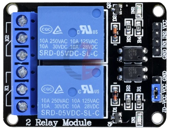
A two-channel relay is an electromechanical device that allows for the control of two separate circuits by a low-power signal. The 5V two-channel relay is particularly suitable for use with microcontrollers like the Arduino UNO, where it can be used to switch higher power loads than the microcontroller can handle directly. Common applications include home automation, such as controlling lights, motors, and other household appliances.
Explore Projects Built with Two Channel Relay 5v


Explore Projects Built with Two Channel Relay 5v
Technical Specifications
Key Technical Details
- Operating Voltage: 5V DC
- Trigger Voltage: 0 - 1.5V (Low Trigger), 2.5 - 5V (High Trigger)
- Max Switching Voltage: 250V AC / 30V DC
- Max Switching Current: 10A AC / 10A DC
- Control Signal: TTL level from microcontrollers
- Isolation: Opto-isolated inputs
Pin Configuration and Descriptions
| Pin Number | Description | Notes |
|---|---|---|
| 1 | VCC | 5V power supply to the relay |
| 2 | GND | Ground |
| 3 | IN1 | Input signal for Relay 1 |
| 4 | IN2 | Input signal for Relay 2 |
| 5 | COM1 | Common pin for Relay 1 |
| 6 | NO1 | Normally Open pin for Relay 1 |
| 7 | NC1 | Normally Closed pin for Relay 1 |
| 8 | COM2 | Common pin for Relay 2 |
| 9 | NO2 | Normally Open pin for Relay 2 |
| 10 | NC2 | Normally Closed pin for Relay 2 |
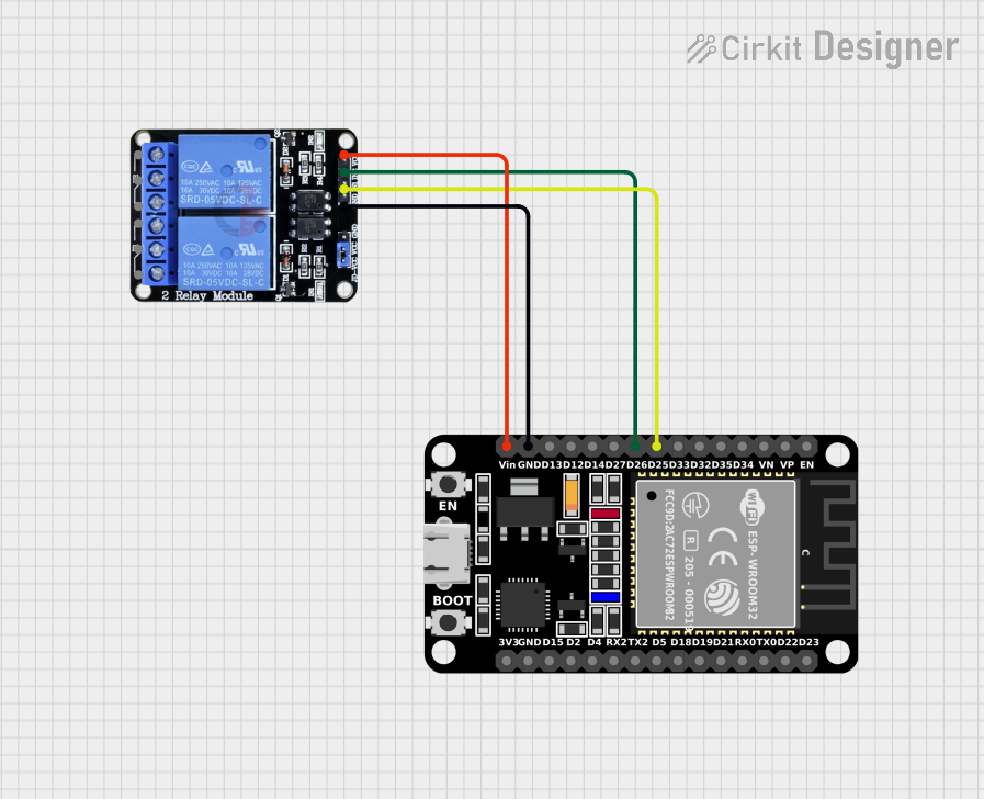
Usage Instructions
How to Use the Component in a Circuit
Powering the Relay:
- Connect the VCC pin to a 5V power supply.
- Connect the GND pin to the ground of the power supply.
Connecting the Control Signal:
- Connect IN1 and IN2 to digital outputs on your microcontroller.
Connecting the Load:
- For each channel, connect the common (COM) pin to the power source for your load.
- Connect the Normally Open (NO) pin to the load if you want the load to be powered when the relay is activated.
- Connect the Normally Closed (NC) pin to the load if you want the load to be powered when the relay is not activated.
Important Considerations and Best Practices
- Ensure that the power ratings of the load do not exceed the relay's maximum switching voltage and current.
- Use flyback diodes when controlling inductive loads to prevent back EMF damage.
- Keep the control signal wires as short as possible to minimize interference.
- Do not touch the relay module when it is in operation.
Example Code for Arduino UNO
// Define relay control pins
const int relayPin1 = 2;
const int relayPin2 = 3;

void setup() {
  // Set relay pins as output
  pinMode(relayPin1, OUTPUT);
  pinMode(relayPin2, OUTPUT);
}

void loop() {
  // Turn on Relay 1
  digitalWrite(relayPin1, HIGH);
  delay(1000); // Wait for 1 second

  // Turn off Relay 1
  digitalWrite(relayPin1, LOW);
  delay(1000); // Wait for 1 second

  // Turn on Relay 2
  digitalWrite(relayPin2, HIGH);
  delay(1000); // Wait for 1 second

  // Turn off Relay 2
  digitalWrite(relayPin2, LOW);
  delay(1000); // Wait for 1 second
}
Troubleshooting and FAQs
Common Issues
- Relay does not switch: Check the control signal and power connections.
- Intermittent operation: Ensure solid connections and that the power supply is stable.
- Clicking sound but no action: Verify that the load does not exceed the relay's ratings.
Solutions and Tips for Troubleshooting
- Double-check wiring against the pin configuration table.
- Use a multimeter to verify the presence of the control signal.
- Ensure the power supply can deliver sufficient current for both the relay and the load.
FAQs
Q: Can I use this relay with a 3.3V microcontroller? A: Yes, but ensure that the trigger voltage threshold is met for reliable operation.
Q: Is it necessary to use an external power supply? A: It is recommended if the load requires more current than the microcontroller can provide.
Q: Can I control the relay with PWM? A: No, the relay requires a steady high or low signal to switch states.