How to Use TB6612FNG motor driver: Examples, Pinouts, and Specs
Introduction
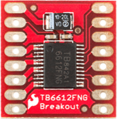
The TB6612FNG is a dual H-bridge motor driver IC designed to control two DC motors or one stepper motor. It supports features such as PWM (Pulse Width Modulation) control, direction control, and current sensing, making it a versatile choice for motor control applications. This compact and efficient IC is widely used in robotics, automation systems, and other projects requiring precise motor control.
Explore Projects Built with TB6612FNG motor driver

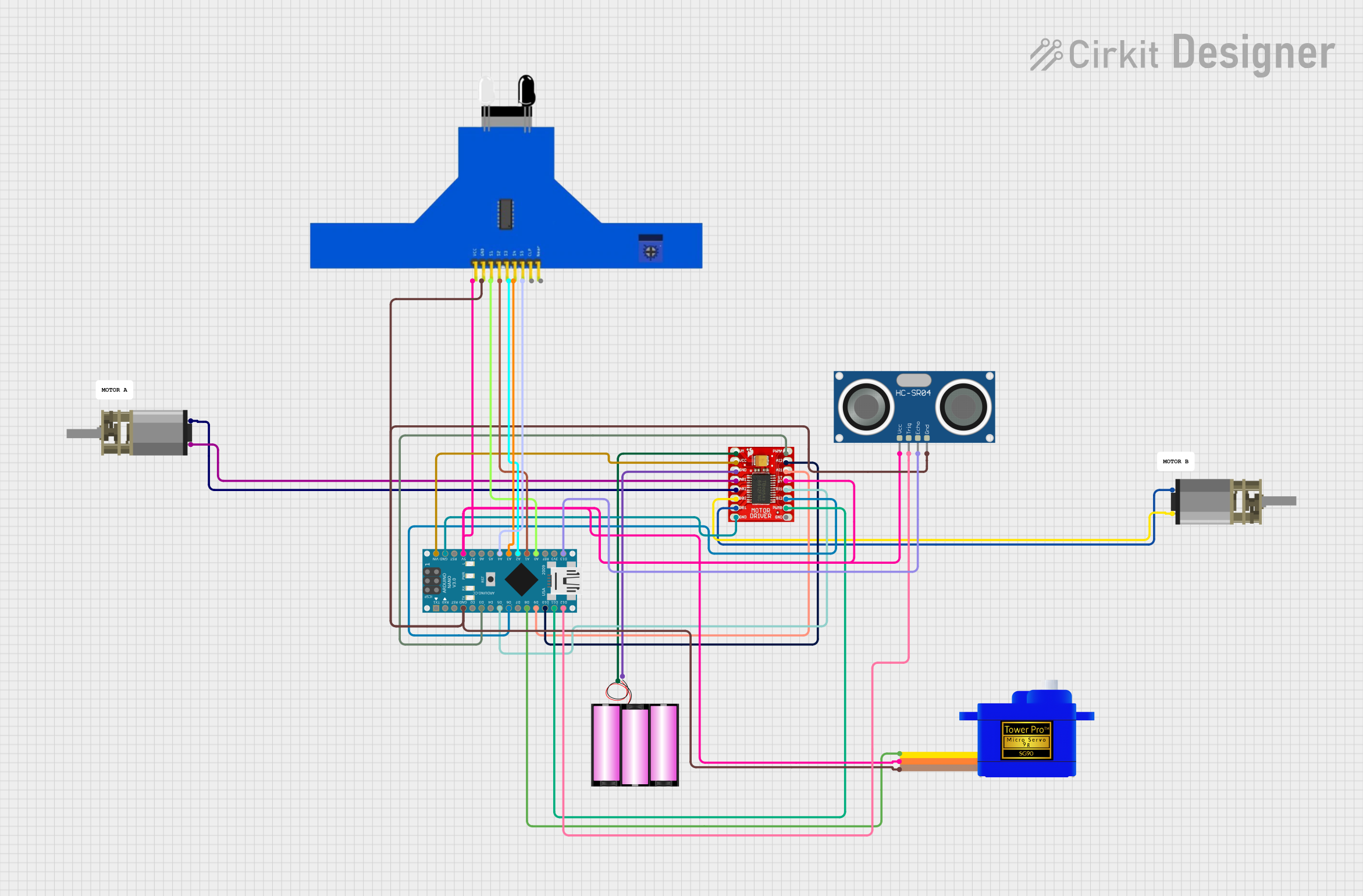
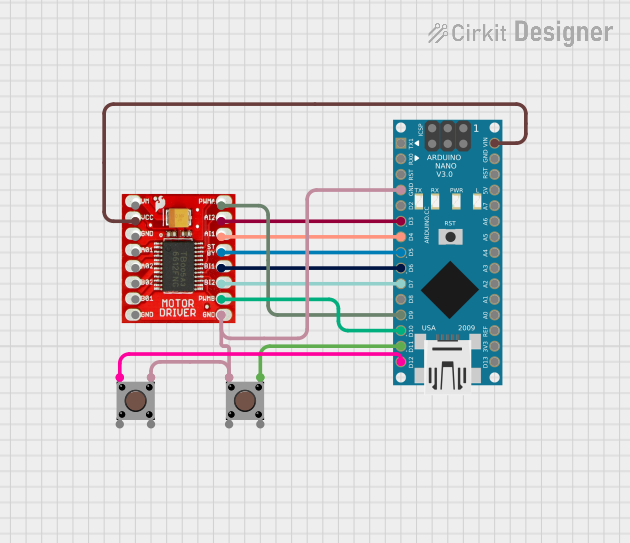
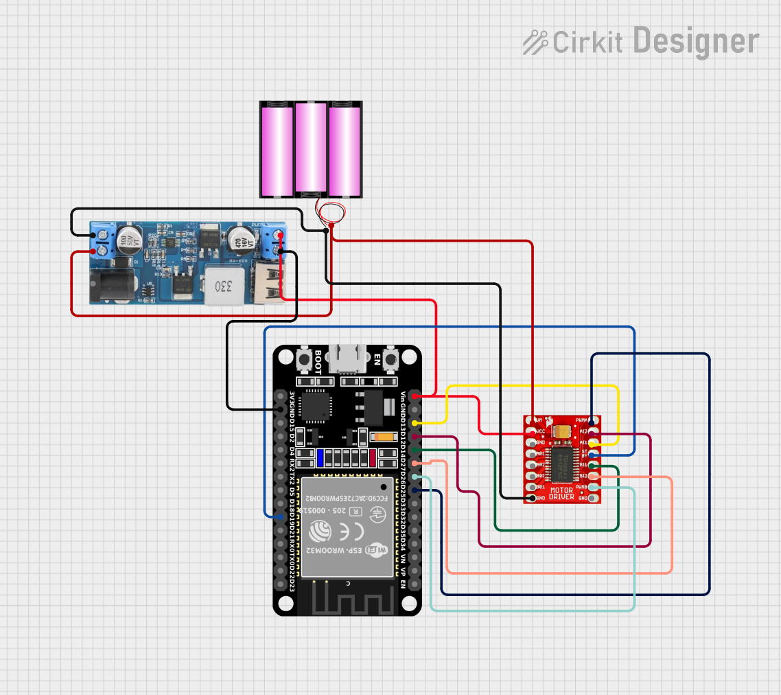
Explore Projects Built with TB6612FNG motor driver
Common Applications
- Robotics (e.g., controlling wheels or robotic arms)
- Automated conveyor systems
- Remote-controlled vehicles
- Stepper motor-based positioning systems
- DIY electronics and Arduino projects
Technical Specifications
The TB6612FNG motor driver offers robust performance with the following key specifications:
| Parameter | Value |
|---|---|
| Operating Voltage (Vcc) | 2.7V to 5.5V |
| Motor Voltage (VM) | 4.5V to 13.5V |
| Output Current (per channel) | 1.2A (continuous), 3.2A (peak) |
| Control Interface | PWM and digital logic inputs |
| Standby Current | 1 µA (typical) |
| Operating Temperature | -20°C to +85°C |
| Package Type | HTSSOP-20 |
Pin Configuration and Descriptions
The TB6612FNG has 20 pins, each serving a specific function. Below is the pinout and description:
| Pin Number | Pin Name | Description |
|---|---|---|
| 1 | AIN1 | Input signal for Motor A direction control |
| 2 | AIN2 | Input signal for Motor A direction control |
| 3 | PWMA | PWM input for Motor A speed control |
| 4 | A01 | Output 1 for Motor A |
| 5 | A02 | Output 2 for Motor A |
| 6 | VM | Motor power supply (4.5V to 13.5V) |
| 7 | GND | Ground |
| 8 | VCC | Logic power supply (2.7V to 5.5V) |
| 9 | STBY | Standby control (active HIGH to enable the IC) |
| 10 | BIN1 | Input signal for Motor B direction control |
| 11 | BIN2 | Input signal for Motor B direction control |
| 12 | PWMB | PWM input for Motor B speed control |
| 13 | B01 | Output 1 for Motor B |
| 14 | B02 | Output 2 for Motor B |
| 15 | NC | No connection |
| 16 | NC | No connection |
| 17 | NC | No connection |
| 18 | NC | No connection |
| 19 | NC | No connection |
| 20 | NC | No connection |
Usage Instructions
How to Use the TB6612FNG in a Circuit
Power Connections:
- Connect the
VMpin to the motor power supply (4.5V to 13.5V). - Connect the
VCCpin to the logic power supply (2.7V to 5.5V). - Connect the
GNDpin to the ground of the circuit.
- Connect the
Motor Connections:
- Connect the motor terminals to the
A01andA02pins for Motor A, andB01andB02pins for Motor B.
- Connect the motor terminals to the
Control Signals:
- Use the
AIN1andAIN2pins to control the direction of Motor A, andBIN1andBIN2for Motor B. - Provide a PWM signal to the
PWMAandPWMBpins to control the speed of Motor A and Motor B, respectively. - Set the
STBYpin HIGH to enable the IC.
- Use the
Direction Control:
- Set
AIN1HIGH andAIN2LOW to rotate Motor A in one direction. - Set
AIN1LOW andAIN2HIGH to rotate Motor A in the opposite direction. - Similarly, use
BIN1andBIN2for Motor B.
- Set
PWM Speed Control:
- Provide a PWM signal (0% to 100% duty cycle) to the
PWMAandPWMBpins to control the speed of the motors.
- Provide a PWM signal (0% to 100% duty cycle) to the
Example: Using TB6612FNG with Arduino UNO
Below is an example Arduino sketch to control two DC motors using the TB6612FNG:
// Define motor control pins
const int AIN1 = 7;  // Motor A direction control pin 1
const int AIN2 = 6;  // Motor A direction control pin 2
const int PWMA = 5;  // Motor A speed control (PWM) pin
const int BIN1 = 4;  // Motor B direction control pin 1
const int BIN2 = 3;  // Motor B direction control pin 2
const int PWMB = 2;  // Motor B speed control (PWM) pin
const int STBY = 8;  // Standby pin

void setup() {
  // Set motor control pins as outputs
  pinMode(AIN1, OUTPUT);
  pinMode(AIN2, OUTPUT);
  pinMode(PWMA, OUTPUT);
  pinMode(BIN1, OUTPUT);
  pinMode(BIN2, OUTPUT);
  pinMode(PWMB, OUTPUT);
  pinMode(STBY, OUTPUT);

  // Enable the motor driver by setting STBY HIGH
  digitalWrite(STBY, HIGH);
}

void loop() {
  // Example: Rotate Motor A forward at 50% speed
  digitalWrite(AIN1, HIGH);  // Set direction
  digitalWrite(AIN2, LOW);
  analogWrite(PWMA, 128);    // Set speed (128 = 50% duty cycle)

  // Example: Rotate Motor B backward at 75% speed
  digitalWrite(BIN1, LOW);   // Set direction
  digitalWrite(BIN2, HIGH);
  analogWrite(PWMB, 192);    // Set speed (192 = 75% duty cycle)

  delay(2000);               // Run motors for 2 seconds

  // Stop both motors
  analogWrite(PWMA, 0);
  analogWrite(PWMB, 0);

  delay(2000);               // Wait for 2 seconds
}
Important Considerations
- Ensure that the motor power supply voltage (
VM) matches the requirements of your motors. - Avoid exceeding the maximum continuous current rating (1.2A per channel) to prevent overheating.
- Use appropriate decoupling capacitors near the
VMandVCCpins to reduce noise and improve stability. - Always set the
STBYpin HIGH to enable the IC before sending control signals.
Troubleshooting and FAQs
Common Issues and Solutions
Motors Not Spinning:
- Ensure the
STBYpin is set HIGH to enable the IC. - Verify that the motor power supply (
VM) and logic power supply (VCC) are connected and within the specified voltage range.
- Ensure the
Motor Spins in the Wrong Direction:
- Check the connections to the
AIN1,AIN2,BIN1, andBIN2pins. - Reverse the logic levels on the direction control pins to change the motor's rotation direction.
- Check the connections to the
Motor Speed is Inconsistent:
- Ensure the PWM signal is stable and within the correct frequency range (typically 20kHz or higher).
- Check for loose connections or insufficient power supply.
IC Overheating:
- Verify that the current drawn by the motors does not exceed the maximum continuous current rating (1.2A per channel).
- Consider adding a heat sink or improving ventilation around the IC.
FAQs
Q: Can the TB6612FNG drive stepper motors?
A: Yes, the TB6612FNG can drive a bipolar stepper motor by controlling the two H-bridges. You will need to sequence the control signals appropriately.
Q: What is the purpose of the STBY pin?
A: The STBY pin is used to enable or disable the IC. Setting it LOW puts the IC in standby mode, reducing power consumption.
Q: Can I use the TB6612FNG with a 3.3V microcontroller?
A: Yes, the TB6612FNG supports logic levels as low as 2.7V, making it compatible with 3.3V microcontrollers.
Q: What is the maximum PWM frequency supported?
A: The TB6612FNG can handle PWM frequencies up to 100kHz, but typical applications use frequencies around 20kHz.