Cirkit Designer Logo
Cirkit Designer
Your all-in-one circuit design IDE
Home / 
Component Documentation

How to Use PCF8574 IO Expansion Board: Examples, Pinouts, and Specs

Image of PCF8574 IO Expansion Board
Cirkit Designer LogoDesign with PCF8574 IO Expansion Board in Cirkit Designer

Introduction

The PCF8574 IO Expansion Board is a versatile module that utilizes the PCF8574T I²C I/O expander chip to increase the number of digital input/output (I/O) pins available to a microcontroller, such as an Arduino or Raspberry Pi. This expansion is particularly useful when the number of built-in I/O pins is insufficient for a given project. The board operates over the I²C bus, allowing multiple devices to be connected to the same bus with only two wires, thus saving valuable pin resources.

Explore Projects Built with PCF8574 IO Expansion Board

Use Cirkit Designer to design, explore, and prototype these projects online. Some projects support real-time simulation. Click "Open Project" to start designing instantly!
Arduino UNO-Based Real-Time Clock with I2C LCD Display and IO Expansion
Image of teste: A project utilizing PCF8574 IO Expansion Board in a practical application
This circuit is an Arduino-based real-time clock and display system. It uses an Arduino UNO to interface with a DS1307 RTC module for timekeeping and a 20x4 I2C LCD to display the current time and date. Additionally, a PCF8574 IO Expansion Board is used to extend the I2C bus for additional I/O operations.
Cirkit Designer LogoOpen Project in Cirkit Designer
ESP32-Based Industrial Control System with RS485 Communication and I2C Interface
Image of DRIVER TESTER : A project utilizing PCF8574 IO Expansion Board in a practical application
This circuit integrates a microcontroller with a display, digital potentiometer, IO expander, and opto-isolator board for signal interfacing and isolation. It includes a UART to RS485 converter for serial communication and a power converter to step down voltage for the system. The circuit is designed for control and communication in an isolated and protected environment.
Cirkit Designer LogoOpen Project in Cirkit Designer
ESP32-Based I2C Communication Hub with Multiplexer and Expander
Image of Lights: A project utilizing PCF8574 IO Expansion Board in a practical application
This circuit features an Olimex ESP32-EVB microcontroller unit (MCU) for processing and connectivity, interfaced with an MCP23017 I/O expander and an Adafruit TCA9548A I2C multiplexer to expand the number of I/O lines and allow multiple I2C devices to communicate with the MCU over the same bus. Pull-up resistors are connected to the I2C lines for proper bus operation, and both the MCP23017 and TCA9548A have their reset lines pulled high, likely for normal operation without external reset control.
Cirkit Designer LogoOpen Project in Cirkit Designer
I2C-Controlled Relay Switching with ESP32 and MCP23017 for Home Automation
Image of Vloerverwarming: A project utilizing PCF8574 IO Expansion Board in a practical application
This circuit appears to be a control system utilizing two MCP23017 I/O expanders interfaced with an Olimex ESP32-EVB microcontroller via I2C communication, as indicated by the SDA and SCL connections with pull-up resistors. The MCP23017 expanders control an 8-channel relay module, allowing the microcontroller to switch various loads, potentially for home automation or industrial control. Additionally, there is an Adafruit ADS1115 16-bit ADC for analog signal measurement, and several heating actuators and a thermostat are connected, suggesting temperature control functionality.
Cirkit Designer LogoOpen Project in Cirkit Designer

Explore Projects Built with PCF8574 IO Expansion Board

Use Cirkit Designer to design, explore, and prototype these projects online. Some projects support real-time simulation. Click "Open Project" to start designing instantly!
Image of teste: A project utilizing PCF8574 IO Expansion Board in a practical application
Arduino UNO-Based Real-Time Clock with I2C LCD Display and IO Expansion
This circuit is an Arduino-based real-time clock and display system. It uses an Arduino UNO to interface with a DS1307 RTC module for timekeeping and a 20x4 I2C LCD to display the current time and date. Additionally, a PCF8574 IO Expansion Board is used to extend the I2C bus for additional I/O operations.
Cirkit Designer LogoOpen Project in Cirkit Designer
Image of DRIVER TESTER : A project utilizing PCF8574 IO Expansion Board in a practical application
ESP32-Based Industrial Control System with RS485 Communication and I2C Interface
This circuit integrates a microcontroller with a display, digital potentiometer, IO expander, and opto-isolator board for signal interfacing and isolation. It includes a UART to RS485 converter for serial communication and a power converter to step down voltage for the system. The circuit is designed for control and communication in an isolated and protected environment.
Cirkit Designer LogoOpen Project in Cirkit Designer
Image of Lights: A project utilizing PCF8574 IO Expansion Board in a practical application
ESP32-Based I2C Communication Hub with Multiplexer and Expander
This circuit features an Olimex ESP32-EVB microcontroller unit (MCU) for processing and connectivity, interfaced with an MCP23017 I/O expander and an Adafruit TCA9548A I2C multiplexer to expand the number of I/O lines and allow multiple I2C devices to communicate with the MCU over the same bus. Pull-up resistors are connected to the I2C lines for proper bus operation, and both the MCP23017 and TCA9548A have their reset lines pulled high, likely for normal operation without external reset control.
Cirkit Designer LogoOpen Project in Cirkit Designer
Image of Vloerverwarming: A project utilizing PCF8574 IO Expansion Board in a practical application
I2C-Controlled Relay Switching with ESP32 and MCP23017 for Home Automation
This circuit appears to be a control system utilizing two MCP23017 I/O expanders interfaced with an Olimex ESP32-EVB microcontroller via I2C communication, as indicated by the SDA and SCL connections with pull-up resistors. The MCP23017 expanders control an 8-channel relay module, allowing the microcontroller to switch various loads, potentially for home automation or industrial control. Additionally, there is an Adafruit ADS1115 16-bit ADC for analog signal measurement, and several heating actuators and a thermostat are connected, suggesting temperature control functionality.
Cirkit Designer LogoOpen Project in Cirkit Designer

Common Applications and Use Cases

  • Expanding I/O capabilities for microcontrollers
  • Home automation systems
  • Robotics and control systems
  • DIY electronics projects

Technical Specifications

Key Technical Details

  • Operating Voltage: 2.5V to 6V
  • I²C Bus Voltage: 5V tolerant
  • Number of I/O Pins: 8
  • Max Output Current per Pin: 25 mA
  • Max Input Current per Pin: 100 mA
  • Address Range: 0x20 to 0x27 (8 addresses selectable via jumpers)

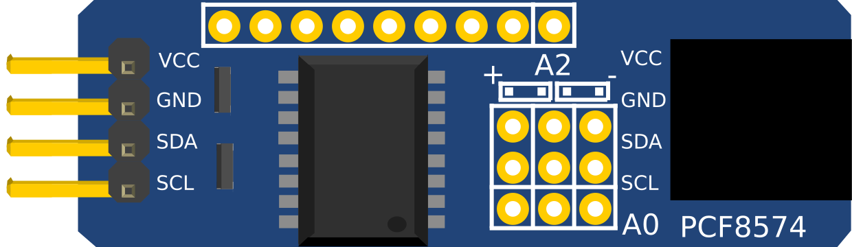
Pin Configuration and Descriptions

Pin Number Pin Name Description
1 P0 I/O pin 0
2 P1 I/O pin 1
3 P2 I/O pin 2
4 P3 I/O pin 3
5 P4 I/O pin 4
6 P5 I/O pin 5
7 P6 I/O pin 6
8 P7 I/O pin 7
9 VSS Ground
10 VDD Power supply (2.5V to 6V)
11 SDA I²C Data line
12 SCL I²C Clock line
13-16 A0-A2 Address pins to set I²C address

Usage Instructions

How to Use the Component in a Circuit

  1. Connect VDD to the power supply (2.5V to 6V) and VSS to ground.
  2. Connect SDA and SCL to the I²C data and clock lines of the microcontroller.
  3. Set the I²C address using the A0, A1, and A2 address pins.
  4. Interface with the PCF8574 using the I²C protocol to read from or write to the I/O pins.

Important Considerations and Best Practices

  • Ensure that the power supply voltage does not exceed the maximum rating of 6V.
  • Use pull-up resistors on the SDA and SCL lines if they are not already present on the microcontroller board.
  • Avoid drawing more than 25 mA from any single I/O pin.
  • When using multiple PCF8574 boards on the same I²C bus, ensure that each has a unique address.

Example Code for Arduino UNO

#include <Wire.h>

// Define the I2C address for the PCF8574 board
#define PCF8574_ADDRESS 0x20

void setup() {
  Wire.begin(); // Initialize I2C protocol
  pinMode(PCF8574_ADDRESS, OUTPUT); // Set all pins of PCF8574 as output
}

void loop() {
  // Turn on all the outputs
  Wire.beginTransmission(PCF8574_ADDRESS);
  Wire.write(0xFF); // Write 0xFF to turn on all pins
  Wire.endTransmission();
  delay(1000);

  // Turn off all the outputs
  Wire.beginTransmission(PCF8574_ADDRESS);
  Wire.write(0x00); // Write 0x00 to turn off all pins
  Wire.endTransmission();
  delay(1000);
}

Troubleshooting and FAQs

Common Issues Users Might Face

  • I²C Communication Failure: Ensure that the SDA and SCL lines are connected properly and that pull-up resistors are in place.
  • Incorrect Addressing: Verify that the address set by the A0-A2 pins matches the address used in the code.
  • Insufficient Power Supply: Make sure that the power supply is within the specified range and capable of delivering sufficient current.

Solutions and Tips for Troubleshooting

  • Use an I²C scanner sketch to confirm the address of the PCF8574 board.
  • Check for soldering issues or loose connections that might affect the I²C communication.
  • If multiple PCF8574 boards are used, ensure that there are no address conflicts.

FAQs

Q: Can I use this board with a 3.3V system? A: Yes, the PCF8574 is 5V tolerant on the I²C bus, but ensure that VDD is within the 2.5V to 6V range.

Q: How many PCF8574 boards can I connect to a single I²C bus? A: You can connect up to 8 PCF8574 boards to a single I²C bus by setting unique addresses using the A0-A2 pins.

Q: Can I use this board for analog signals? A: No, the PCF8574 provides digital I/O expansion only. It cannot be used for analog signals.