
How to Use Voltage sensor: Examples, Pinouts, and Specs
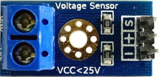
 Design with Voltage sensor in Cirkit Designer
Introduction
The Einstronic 25V Voltage Sensor is a compact and efficient device designed to measure the electrical potential difference between two points in a circuit. It provides real-time voltage readings, making it an essential tool for monitoring and control in various electronic applications. This sensor is particularly useful in battery monitoring, power supply testing, and embedded systems where voltage measurement is critical.
Explore Projects Built with Voltage sensor
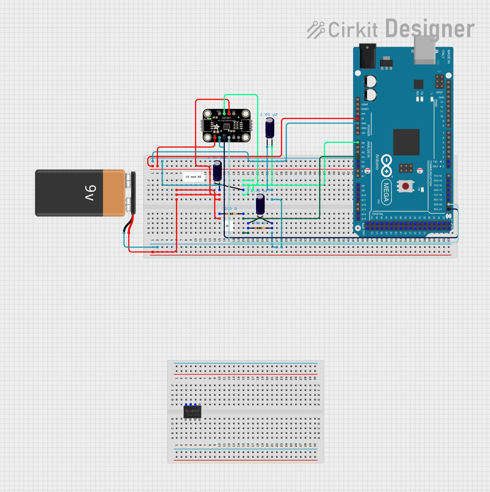 Open Project in Cirkit Designer
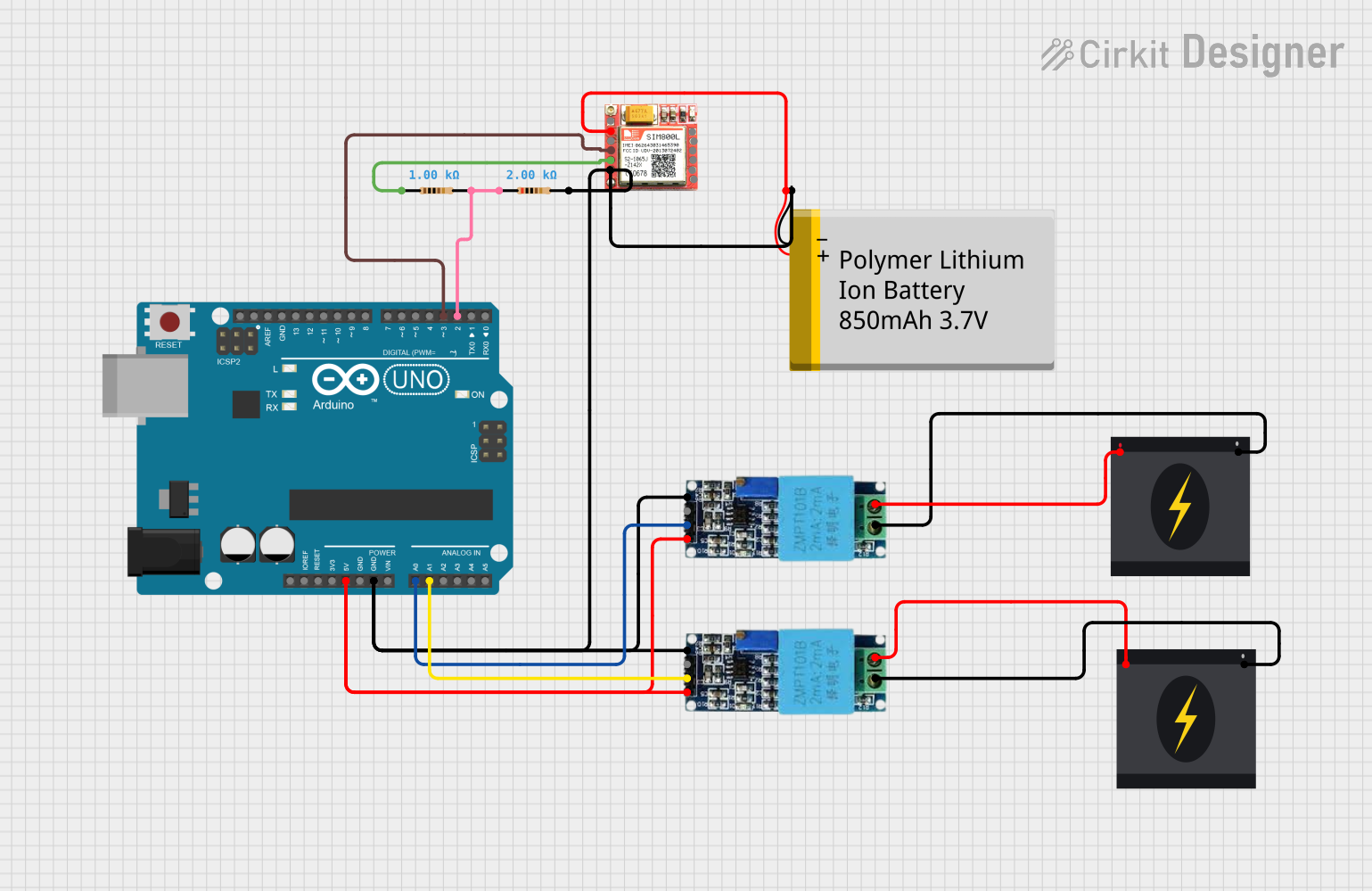 Open Project in Cirkit Designer
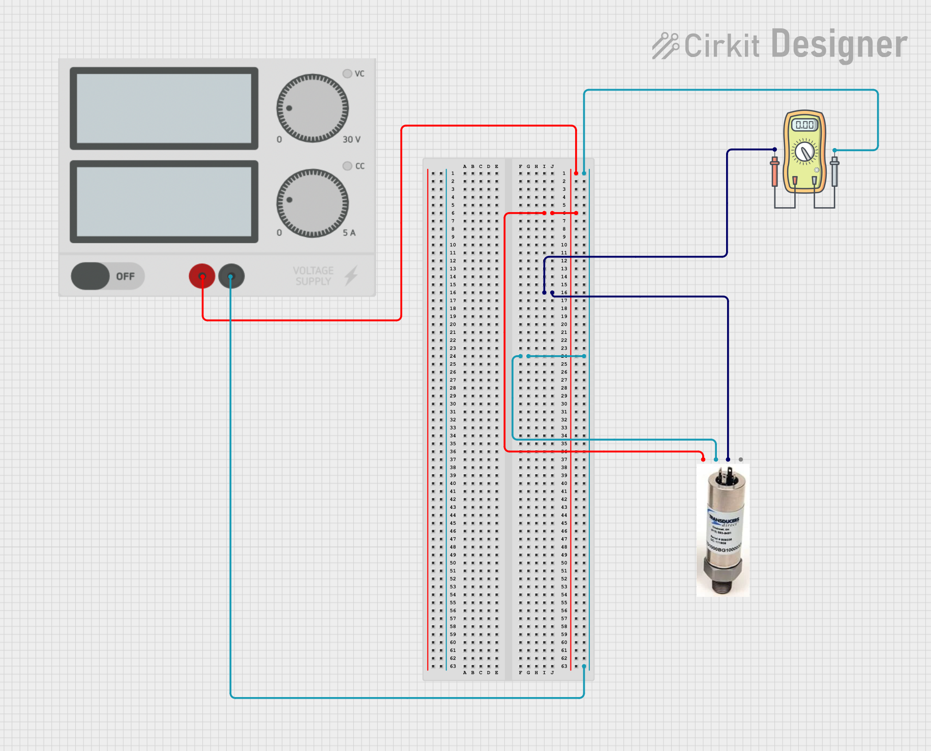 Open Project in Cirkit Designer
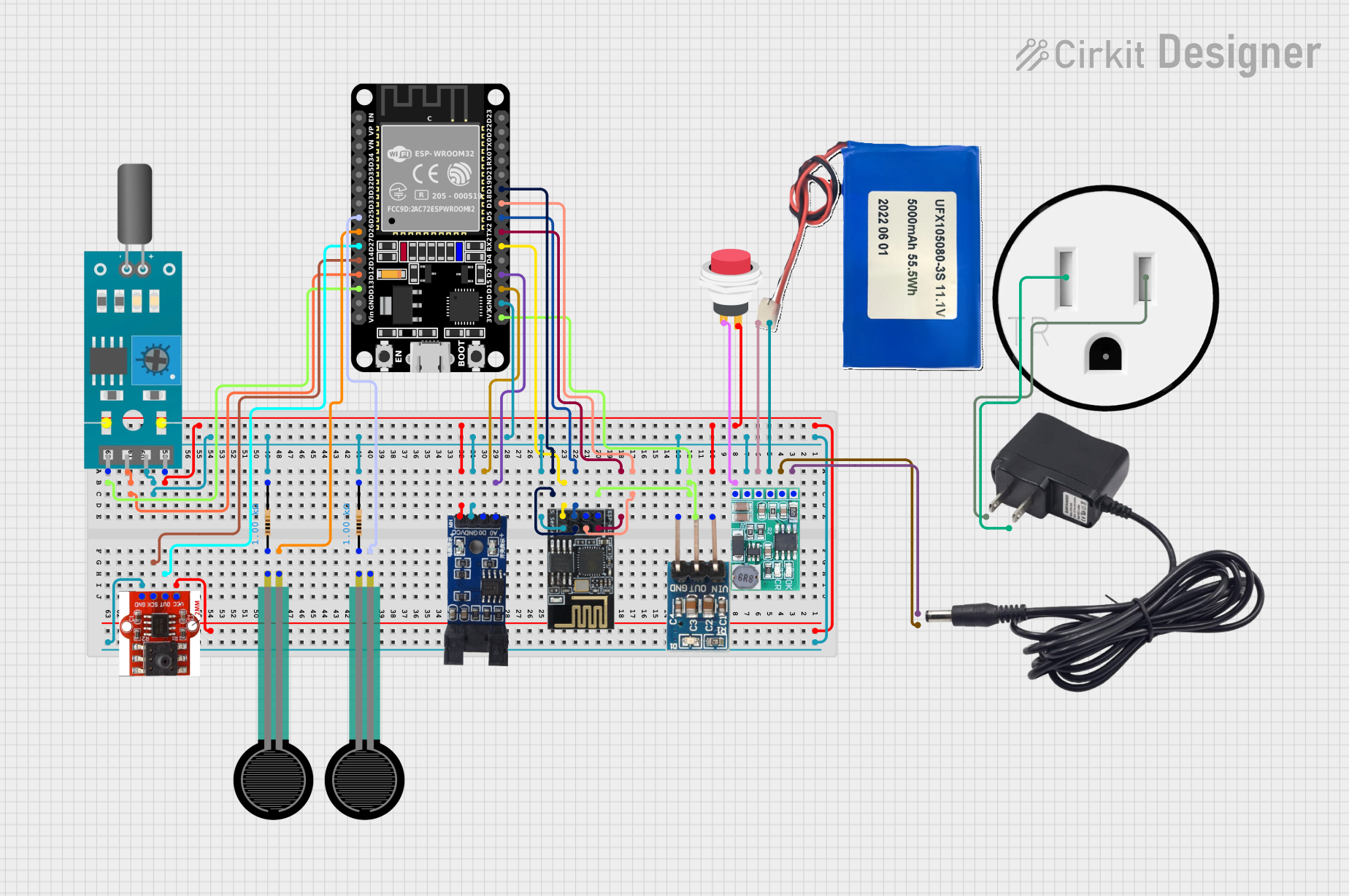 Open Project in Cirkit Designer
Explore Projects Built with Voltage sensor
Open Project in Cirkit DesignerOpen Project in Cirkit DesignerOpen Project in Cirkit DesignerOpen Project in Cirkit DesignerCommon Applications and Use Cases
- Battery voltage monitoring in IoT devices
- Power supply testing and diagnostics
- Voltage measurement in robotics and automation systems
- Integration with microcontrollers (e.g., Arduino, Raspberry Pi) for real-time monitoring
- Educational projects and prototyping
Technical Specifications
The following table outlines the key technical details of the Einstronic 25V Voltage Sensor:
| Parameter | Specification |
|---|---|
| Manufacturer | Einstronic |
| Part ID | 25V Voltage Sensor |
| Input Voltage Range | 0V to 25V |
| Output Voltage Range | 0V to 5V (scaled for microcontroller) |
| Measurement Accuracy | ±1% |
| Operating Voltage | 3.3V or 5V DC |
| Operating Current | <10mA |
| Dimensions | 30mm x 15mm x 10mm |
| Weight | 5g |
Pin Configuration and Descriptions
The Einstronic 25V Voltage Sensor has a simple pinout, as described in the table below:
| Pin Name | Description |
|---|---|
VCC |
Power supply input (3.3V or 5V DC) |
GND |
Ground connection |
VIN |
Voltage input to be measured (connect to the positive terminal of the circuit) |
VOUT |
Scaled voltage output (connect to an analog input pin of a microcontroller) |
Usage Instructions
How to Use the Component in a Circuit
- Power the Sensor: Connect the
VCCpin to a 3.3V or 5V DC power source and theGNDpin to the ground. - Connect the Voltage to Be Measured: Attach the positive terminal of the voltage source to the
VINpin and the negative terminal to theGNDpin. - Read the Scaled Output: The
VOUTpin provides a scaled-down voltage (0-5V) proportional to the input voltage (0-25V). Connect this pin to an analog input pin of a microcontroller (e.g., Arduino) to read the voltage.
Important Considerations and Best Practices
- Ensure the input voltage does not exceed 25V to avoid damaging the sensor.
- Use proper grounding to minimize noise and ensure accurate readings.
- If using with a 3.3V microcontroller, ensure the
VOUTpin does not exceed the ADC input voltage limit. - For higher accuracy, calibrate the sensor by comparing its output with a known reference voltage.
Example Code for Arduino UNO
Below is an example Arduino sketch to read and display the voltage using the Einstronic 25V Voltage Sensor:
// Define the analog pin connected to the VOUT pin of the voltage sensor
const int sensorPin = A0;

// Define the scaling factor (based on the sensor's 0-25V input range and 0-5V output range)
const float scalingFactor = 5.0 / 1023.0 * 5.0;

void setup() {
  Serial.begin(9600); // Initialize serial communication at 9600 baud
}

void loop() {
  int sensorValue = analogRead(sensorPin); // Read the analog value from the sensor
  float voltage = sensorValue * scalingFactor; // Convert the analog value to voltage

  // Print the measured voltage to the Serial Monitor
  Serial.print("Measured Voltage: ");
  Serial.print(voltage);
  Serial.println(" V");

  delay(1000); // Wait for 1 second before taking the next reading
}
Note: The scaling factor in the code assumes a 10-bit ADC (0-1023) and a 5V reference voltage. Adjust the scaling factor if using a different ADC resolution or reference voltage.
Troubleshooting and FAQs
Common Issues and Solutions
No Output Voltage on
VOUTPin:- Ensure the sensor is powered correctly (check
VCCandGNDconnections). - Verify that the input voltage on
VINis within the 0-25V range.
- Ensure the sensor is powered correctly (check
Inaccurate Voltage Readings:
- Check for loose or improper connections.
- Calibrate the sensor using a known reference voltage.
- Ensure the microcontroller's ADC reference voltage matches the expected value.
Microcontroller Not Detecting Voltage:
- Confirm that the
VOUTpin is connected to the correct analog input pin. - Verify that the microcontroller's ADC is enabled and configured correctly.
- Confirm that the
FAQs
Q: Can this sensor measure negative voltages?
A: No, the sensor is designed to measure positive voltages only (0-25V). Measuring negative voltages may damage the sensor.
Q: Can I use this sensor with a 3.3V microcontroller?
A: Yes, the sensor can operate at 3.3V. However, ensure the VOUT pin voltage does not exceed the ADC input voltage limit of the microcontroller.
Q: How do I improve measurement accuracy?
A: Use shorter wires to reduce noise, ensure proper grounding, and calibrate the sensor with a multimeter or reference voltage source.
Q: Is the sensor suitable for AC voltage measurement?
A: No, the sensor is designed for DC voltage measurement only. For AC voltage, use a dedicated AC voltage sensor or rectifier circuit.
By following this documentation, users can effectively integrate the Einstronic 25V Voltage Sensor into their projects for reliable and accurate voltage measurement.