
How to Use Adafruit 1.2 Inch 8x8 LED Matrix Backpack - Red: Examples, Pinouts, and Specs
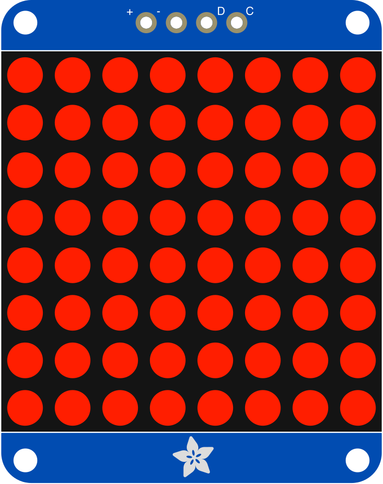
 Design with Adafruit 1.2 Inch 8x8 LED Matrix Backpack - Red in Cirkit Designer
Introduction
The Adafruit 1.2 Inch 8x8 LED Matrix Backpack - Red (Manufacturer Part ID: 1049) is a compact and versatile LED display module. It features an 8x8 grid of bright red LEDs, making it ideal for displaying simple graphics, scrolling text, or numeric data. The module is equipped with an I2C interface, simplifying integration with microcontrollers such as Arduino, Raspberry Pi, and others. Its small size and ease of use make it a popular choice for hobbyists and professionals alike.
Explore Projects Built with Adafruit 1.2 Inch 8x8 LED Matrix Backpack - Red
 Open Project in Cirkit Designer
 Open Project in Cirkit Designer
 Open Project in Cirkit Designer
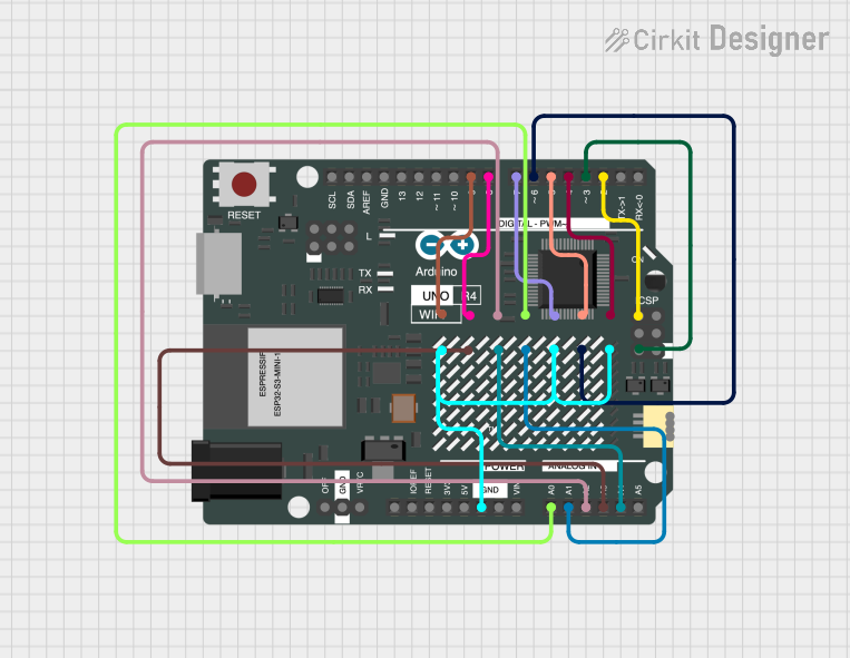 Open Project in Cirkit Designer
Explore Projects Built with Adafruit 1.2 Inch 8x8 LED Matrix Backpack - Red
Open Project in Cirkit DesignerOpen Project in Cirkit DesignerOpen Project in Cirkit DesignerOpen Project in Cirkit DesignerCommon Applications
- Digital clocks and timers
- Scrolling text displays
- Simple animations or graphics
- Status indicators for IoT devices
- Educational projects and prototyping
Technical Specifications
Below are the key technical details for the Adafruit 1.2 Inch 8x8 LED Matrix Backpack:
| Specification | Details |
|---|---|
| Manufacturer | Adafruit |
| Manufacturer Part ID | 1049 |
| LED Color | Red |
| Matrix Size | 8x8 (64 LEDs) |
| Communication Protocol | I2C |
| Operating Voltage | 5V DC |
| Current Consumption | ~40mA (typical, varies with LED usage) |
| Dimensions | 1.2 inches x 1.2 inches |
| Mounting | PCB holes for secure attachment |
Pin Configuration
The module has a 4-pin header for I2C communication and power. Below is the pinout:
| Pin | Name | Description |
|---|---|---|
| 1 | GND | Ground (0V reference) |
| 2 | VCC | Power supply (5V DC) |
| 3 | SDA | I2C data line |
| 4 | SCL | I2C clock line |
Usage Instructions
Connecting the Module
- Power Supply: Connect the
VCCpin to a 5V power source and theGNDpin to ground. - I2C Interface: Connect the
SDAandSCLpins to the corresponding I2C pins on your microcontroller:- For Arduino UNO:
SDA→ A4SCL→ A5
- For other microcontrollers, refer to their I2C pinout documentation.
- For Arduino UNO:
- Pull-Up Resistors: Ensure that your I2C bus has pull-up resistors (typically 4.7kΩ) on the
SDAandSCLlines. Many microcontroller boards include these by default.
Installing the Required Library
To control the LED matrix, you need the Adafruit LED Backpack Library:
- Open the Arduino IDE.
- Go to Sketch > Include Library > Manage Libraries.
- Search for "Adafruit LED Backpack" and click Install.
- Also, install the "Adafruit GFX Library" for graphics support.
Example Code
Below is an example Arduino sketch to display a scrolling message on the LED matrix:
#include <Wire.h>
#include <Adafruit_GFX.h>
#include <Adafruit_LEDBackpack.h>

// Create an instance of the LED matrix
Adafruit_8x8matrix matrix = Adafruit_8x8matrix();

void setup() {
  // Initialize the matrix
  matrix.begin(0x70); // Default I2C address is 0x70
  matrix.setBrightness(10); // Set brightness (0-15)
}

void loop() {
  // Display a scrolling message
  static const uint8_t message[] = "HELLO ";
  static int8_t position = 8; // Start off-screen

  matrix.clear(); // Clear the display
  matrix.setCursor(position, 0); // Set text position
  matrix.print((char *)message); // Print the message
  matrix.writeDisplay(); // Update the display

  delay(200); // Pause for scrolling effect
  position--; // Move text left

  // Reset position when the message scrolls off-screen
  if (position < -6 * sizeof(message)) {
    position = 8;
  }
}
Important Considerations
- I2C Address: The default I2C address is
0x70. If you have multiple devices on the same I2C bus, you can change the address by soldering the address jumpers on the back of the module. - Brightness: Use
setBrightness()to adjust the brightness level (0-15). Higher brightness increases power consumption. - Power Supply: Ensure your power source can supply sufficient current, especially if multiple LEDs are lit simultaneously.
Troubleshooting and FAQs
Common Issues
No Display Output
- Cause: Incorrect wiring or no power.
- Solution: Double-check all connections, especially
VCCandGND.
Flickering LEDs
- Cause: Insufficient power supply or loose connections.
- Solution: Use a stable 5V power source and ensure all connections are secure.
I2C Communication Failure
- Cause: Incorrect I2C address or missing pull-up resistors.
- Solution: Verify the I2C address (default is
0x70) and ensure pull-up resistors are present.
Dim LEDs
- Cause: Low brightness setting or insufficient power.
- Solution: Increase brightness using
setBrightness()and check the power supply.
FAQs
Can I use this module with a 3.3V microcontroller?
- Yes, but you must ensure the I2C lines are 3.3V compatible. The module itself requires a 5V power supply.
How do I change the I2C address?
- Solder the address jumpers on the back of the module to set a new address. Refer to the Adafruit documentation for the address mapping.
Can I daisy-chain multiple LED matrices?
- Yes, but each matrix must have a unique I2C address.
What is the maximum viewing distance?
- The display is best viewed from a distance of up to 2-3 meters.
By following this documentation, you can effectively integrate and use the Adafruit 1.2 Inch 8x8 LED Matrix Backpack in your projects.