Cirkit Designer Logo
Cirkit Designer
Your all-in-one circuit design IDE
Home / 
Component Documentation

How to Use 5V 8Channel Relay: Examples, Pinouts, and Specs

Image of 5V 8Channel Relay
Cirkit Designer LogoDesign with 5V 8Channel Relay in Cirkit Designer

Introduction

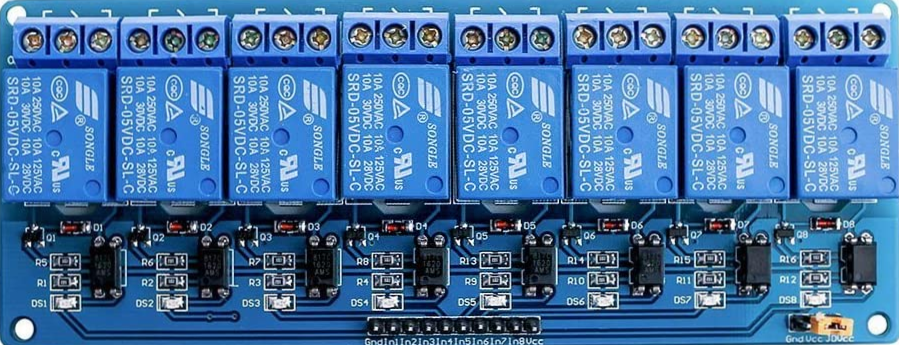
The 5V 8-Channel Relay Module is an electronic device that enables control of multiple high-power circuits using low-power signals from a microcontroller like an Arduino. Each relay serves as an electrically operated switch that can be turned on or off to control devices such as motors, lights, and other appliances that require higher voltages and currents than a microcontroller can provide directly.

Explore Projects Built with 5V 8Channel Relay

Use Cirkit Designer to design, explore, and prototype these projects online. Some projects support real-time simulation. Click "Open Project" to start designing instantly!
ESP32-Powered 8-Channel Relay Controller with Wi-Fi Connectivity
Image of Olimex ESP32-POE2 4Ch X 2 Switches: A project utilizing 5V 8Channel Relay in a practical application
This circuit features an ESP32 microcontroller connected to an 8-channel relay module. The ESP32 controls the relay channels via its GPIO pins, allowing for the switching of external devices or loads through the relays.
Cirkit Designer LogoOpen Project in Cirkit Designer
ESP32-Powered Wi-Fi Controlled 8-Channel Relay Module
Image of Olimex ESP32-POE2 8Ch Switch and Sensors: A project utilizing 5V 8Channel Relay in a practical application
This circuit features an ESP32 microcontroller connected to an 8-channel relay module. The ESP32 controls the relay channels via its GPIO pins, allowing it to switch multiple external devices on and off. The ESP32 also provides power to the relay module.
Cirkit Designer LogoOpen Project in Cirkit Designer
Wi-Fi Controlled Smart Relay Switch with ESP8266 and MCP23017
Image of Bed Room: A project utilizing 5V 8Channel Relay in a practical application
This circuit is designed to control an 8-channel relay module via an ESP8266 microcontroller, which interfaces with an MCP23017 I/O expander over I2C. The ESP8266 connects to a WiFi network and subscribes to MQTT topics to receive commands for toggling the relays. Additionally, there are toggle switches connected to the MCP23017 that allow manual control of the relays, with the system's state being reported back via MQTT.
Cirkit Designer LogoOpen Project in Cirkit Designer
Battery-Powered 4-Channel Relay Control with LED Indicators
Image of RELLAY BOARD TEST: A project utilizing 5V 8Channel Relay in a practical application
This circuit consists of a 5V battery powering a 4-channel relay module, which controls four LEDs (red, yellow, green, and blue) through individual resistors. Each relay channel is activated by a corresponding SPST toggle switch, allowing manual control of the LEDs.
Cirkit Designer LogoOpen Project in Cirkit Designer

Explore Projects Built with 5V 8Channel Relay

Use Cirkit Designer to design, explore, and prototype these projects online. Some projects support real-time simulation. Click "Open Project" to start designing instantly!
Image of Olimex ESP32-POE2 4Ch X 2 Switches: A project utilizing 5V 8Channel Relay in a practical application
ESP32-Powered 8-Channel Relay Controller with Wi-Fi Connectivity
This circuit features an ESP32 microcontroller connected to an 8-channel relay module. The ESP32 controls the relay channels via its GPIO pins, allowing for the switching of external devices or loads through the relays.
Cirkit Designer LogoOpen Project in Cirkit Designer
Image of Olimex ESP32-POE2 8Ch Switch and Sensors: A project utilizing 5V 8Channel Relay in a practical application
ESP32-Powered Wi-Fi Controlled 8-Channel Relay Module
This circuit features an ESP32 microcontroller connected to an 8-channel relay module. The ESP32 controls the relay channels via its GPIO pins, allowing it to switch multiple external devices on and off. The ESP32 also provides power to the relay module.
Cirkit Designer LogoOpen Project in Cirkit Designer
Image of Bed Room: A project utilizing 5V 8Channel Relay in a practical application
Wi-Fi Controlled Smart Relay Switch with ESP8266 and MCP23017
This circuit is designed to control an 8-channel relay module via an ESP8266 microcontroller, which interfaces with an MCP23017 I/O expander over I2C. The ESP8266 connects to a WiFi network and subscribes to MQTT topics to receive commands for toggling the relays. Additionally, there are toggle switches connected to the MCP23017 that allow manual control of the relays, with the system's state being reported back via MQTT.
Cirkit Designer LogoOpen Project in Cirkit Designer
Image of RELLAY BOARD TEST: A project utilizing 5V 8Channel Relay in a practical application
Battery-Powered 4-Channel Relay Control with LED Indicators
This circuit consists of a 5V battery powering a 4-channel relay module, which controls four LEDs (red, yellow, green, and blue) through individual resistors. Each relay channel is activated by a corresponding SPST toggle switch, allowing manual control of the LEDs.
Cirkit Designer LogoOpen Project in Cirkit Designer

Common Applications and Use Cases

  • Home automation systems
  • Industrial controls
  • Robotics
  • Power supply control

Technical Specifications

Key Technical Details

  • Operating Voltage: 5V DC
  • Relay Output: 250V AC up to 10A or 30V DC up to 10A per channel
  • Control Signal: TTL level from 3.3V to 5V
  • Indicator LEDs: LED for each relay's status

Pin Configuration and Descriptions

Pin Number Description Type
1 IN1 Input
2 IN2 Input
3 IN3 Input
4 IN4 Input
5 IN5 Input
6 IN6 Input
7 IN7 Input
8 IN8 Input
9 GND Ground
10 VCC Power
11 JD-VCC Relay Power

Note: IN1 to IN8 are the control inputs for each relay. VCC is for the logic part, and JD-VCC is for the relay power. GND should be connected to the microcontroller ground.

Usage Instructions

How to Use the Component in a Circuit

  1. Power Connections:

    • Connect the JD-VCC pin to an external 5V power supply if available.
    • Connect the VCC pin to the 5V output from the microcontroller.
    • Connect the GND pin to the ground of the microcontroller.
  2. Input Signal:

    • Connect IN1 to IN8 to the digital output pins on the microcontroller.
  3. Load Connections:

    • Connect the high-power device to the Normally Open (NO) and Common (COM) terminals of the relay.

Important Considerations and Best Practices

  • Ensure the power supply can handle the current required by all relays if activated simultaneously.
  • Use flyback diodes across inductive loads to prevent back EMF damage.
  • Avoid running high voltage wires close to low voltage control wires to prevent interference.

Example Code for Arduino UNO

// Define relay control pins
const int relayPins[] = {2, 3, 4, 5, 6, 7, 8, 9};

void setup() {
  // Initialize all relay control pins as outputs
  for (int i = 0; i < 8; i++) {
    pinMode(relayPins[i], OUTPUT);
    digitalWrite(relayPins[i], HIGH); // Relays are active LOW
  }
}

void loop() {
  // Example: Turn on each relay for 1 second, then off
  for (int i = 0; i < 8; i++) {
    digitalWrite(relayPins[i], LOW); // Activate relay
    delay(1000);                      // Wait for 1 second
    digitalWrite(relayPins[i], HIGH); // Deactivate relay
    delay(1000);                      // Wait for 1 second
  }
}

Troubleshooting and FAQs

Common Issues

  • Relay not activating: Check the control signal voltage and connections.
  • Intermittent operation: Ensure a stable power supply and check for loose connections.
  • Noise issues: Use shielded cables for high voltage lines and keep them away from low voltage control lines.

Solutions and Tips for Troubleshooting

  • Verify that the input signal is within the TTL level range.
  • Check the power supply to the JD-VCC pin if using an external source.
  • Ensure that the current draw of the connected devices does not exceed the relay rating.

FAQs

Q: Can I control the relays with a 3.3V signal? A: Yes, the control signal is TTL compatible and can be triggered with a 3.3V signal.

Q: Do I need to use all eight relays? A: No, you can use as many or as few relays as your application requires.

Q: Can I power the module using the 5V from the Arduino? A: Yes, for low current applications. However, for multiple or high-current relays, an external power supply is recommended.

Q: How do I know if a relay is on or off? A: Each relay has an indicator LED that lights up when the relay is activated (ON).

Q: Is it safe to control mains voltage with this relay module? A: While the relay can switch mains voltage, ensure you have proper knowledge of electrical safety and take necessary precautions. If unsure, consult a professional.