How to Use 12V 10A PWM DC Motor Speed Controller: Examples, Pinouts, and Specs
Introduction
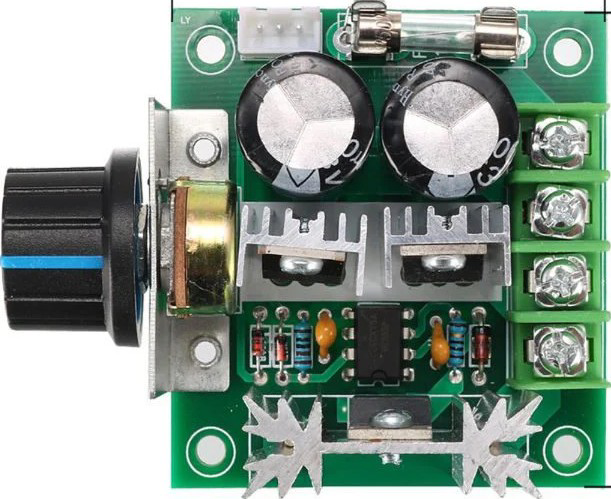
The 12V 10A PWM DC Motor Speed Controller is a versatile device designed to regulate the speed of DC motors by employing Pulse Width Modulation (PWM) techniques. By varying the duty cycle of the PWM signal, this controller adjusts the effective voltage and current supplied to the motor, enabling precise speed control. It is capable of handling up to 10A of current at a voltage of 12V, making it suitable for a wide range of motor control applications.
Explore Projects Built with 12V 10A PWM DC Motor Speed Controller


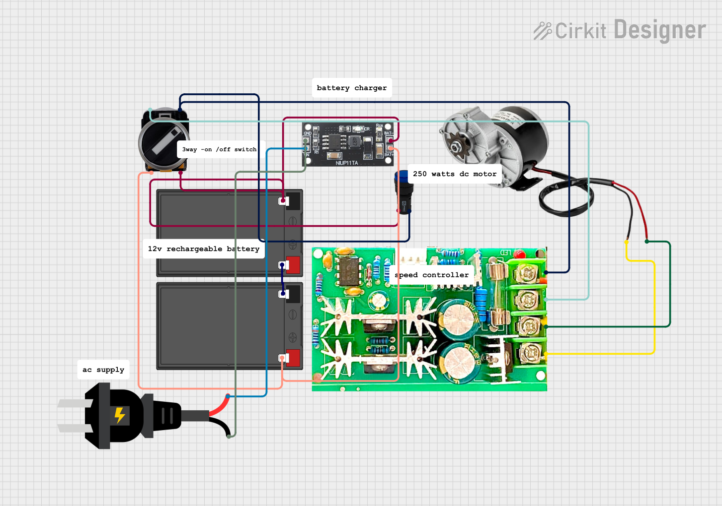
Explore Projects Built with 12V 10A PWM DC Motor Speed Controller
Common Applications and Use Cases
- Robotics: Controlling the speed of DC motors in robotic systems.
- Electric vehicles: Adjusting motor speed in small electric vehicles or scooters.
- Industrial automation: Regulating conveyor belts or other motorized systems.
- DIY projects: Custom motorized projects requiring speed control.
- Fans and pumps: Adjusting the speed of fans or pumps for energy efficiency.
Technical Specifications
The following table outlines the key technical details of the 12V 10A PWM DC Motor Speed Controller:
| Parameter | Value |
|---|---|
| Input Voltage | 12V DC |
| Maximum Current | 10A |
| Control Method | Pulse Width Modulation (PWM) |
| PWM Frequency | 15 kHz (typical) |
| Duty Cycle Range | 0% to 100% |
| Efficiency | ≥ 90% |
| Operating Temperature | -20°C to 60°C |
| Dimensions | Varies by model (e.g., 60x40x25 mm) |
Pin Configuration and Descriptions
The motor speed controller typically has the following terminals for connections:
| Pin/Terminal | Description |
|---|---|
| VIN+ | Positive input voltage terminal (connect to 12V DC power supply). |
| VIN- | Negative input voltage terminal (connect to ground of the power supply). |
| MOTOR+ | Positive output terminal (connect to the positive terminal of the DC motor). |
| MOTOR- | Negative output terminal (connect to the negative terminal of the DC motor). |
| Control Knob | Potentiometer for adjusting the PWM duty cycle and motor speed. |
Usage Instructions
How to Use the Component in a Circuit
Power Supply Connection:
- Connect the VIN+ terminal to the positive terminal of a 12V DC power supply.
- Connect the VIN- terminal to the ground of the power supply.
Motor Connection:
- Connect the MOTOR+ terminal to the positive terminal of the DC motor.
- Connect the MOTOR- terminal to the negative terminal of the DC motor.
Speed Adjustment:
- Use the control knob (potentiometer) to adjust the motor speed. Turning the knob clockwise typically increases the speed, while turning it counterclockwise decreases the speed.
Testing:
- Power on the circuit and observe the motor's behavior. Adjust the control knob to verify smooth speed control.
Important Considerations and Best Practices
- Current Rating: Ensure the motor's current draw does not exceed the controller's 10A limit. Use a fuse or circuit breaker for added protection.
- Heat Dissipation: The controller may generate heat during operation. Use a heatsink or ensure proper ventilation to prevent overheating.
- Polarity: Double-check the polarity of all connections to avoid damage to the controller or motor.
- PWM Frequency: The default PWM frequency is typically 15 kHz, which is suitable for most DC motors. Avoid modifying the frequency unless necessary.
- Power Supply: Use a stable and regulated 12V DC power supply to ensure consistent performance.
Example: Connecting to an Arduino UNO
The 12V 10A PWM DC Motor Speed Controller can be controlled via an Arduino UNO by replacing the manual potentiometer with a PWM signal from the Arduino. Below is an example code snippet:
// Example code to control a 12V 10A PWM DC Motor Speed Controller using Arduino UNO
// The PWM signal is generated on pin 9 to control motor speed.

const int pwmPin = 9; // PWM output pin connected to the controller's input

void setup() {
  pinMode(pwmPin, OUTPUT); // Set pin 9 as an output
}

void loop() {
  // Gradually increase motor speed
  for (int speed = 0; speed <= 255; speed++) {
    analogWrite(pwmPin, speed); // Write PWM value (0-255)
    delay(20); // Small delay for smooth acceleration
  }

  delay(1000); // Run at full speed for 1 second

  // Gradually decrease motor speed
  for (int speed = 255; speed >= 0; speed--) {
    analogWrite(pwmPin, speed); // Write PWM value (0-255)
    delay(20); // Small delay for smooth deceleration
  }

  delay(1000); // Pause before repeating the cycle
}
Note: Ensure the Arduino's ground is connected to the controller's ground (VIN-).
Troubleshooting and FAQs
Common Issues and Solutions
Motor Does Not Run:
- Cause: Incorrect wiring or loose connections.
- Solution: Double-check all connections, ensuring proper polarity and secure terminals.
Motor Runs at Full Speed Only:
- Cause: Faulty potentiometer or incorrect PWM signal.
- Solution: Test the potentiometer for proper operation or verify the PWM signal from the Arduino.
Controller Overheats:
- Cause: Excessive current draw or poor ventilation.
- Solution: Ensure the motor's current is within the 10A limit and improve heat dissipation.
Motor Stutters or Jerks:
- Cause: Insufficient power supply or unstable PWM signal.
- Solution: Use a stable 12V DC power supply and verify the PWM signal's integrity.
FAQs
Q: Can I use this controller with a 24V motor?
A: No, this controller is designed for 12V DC motors only. Using a higher voltage may damage the controller.Q: Can I control multiple motors with this controller?
A: No, this controller is designed for a single motor. For multiple motors, use separate controllers.Q: What happens if the motor draws more than 10A?
A: The controller may overheat or fail. Use a motor with a current draw within the 10A limit.Q: Can I replace the potentiometer with an external PWM signal?
A: Yes, you can replace the potentiometer with a PWM signal from a microcontroller like an Arduino. Ensure the PWM signal is compatible with the controller's input.
This concludes the documentation for the 12V 10A PWM DC Motor Speed Controller.