How to Use Adafruit ItsyBitsy nRF52840: Examples, Pinouts, and Specs
Introduction
The Adafruit ItsyBitsy nRF52840 is a small and powerful microcontroller board that harnesses the capabilities of the Nordic nRF52840 chipset. This board is equipped with a 32-bit ARM Cortex-M4F processor, which provides ample computational power for a wide range of applications. With built-in USB support, Bluetooth Low Energy (BLE), and a rich set of I/O options, the ItsyBitsy nRF52840 is an ideal choice for projects that require wireless connectivity, such as wearable devices, smart home applications, and IoT prototypes.
Explore Projects Built with Adafruit ItsyBitsy nRF52840
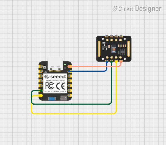

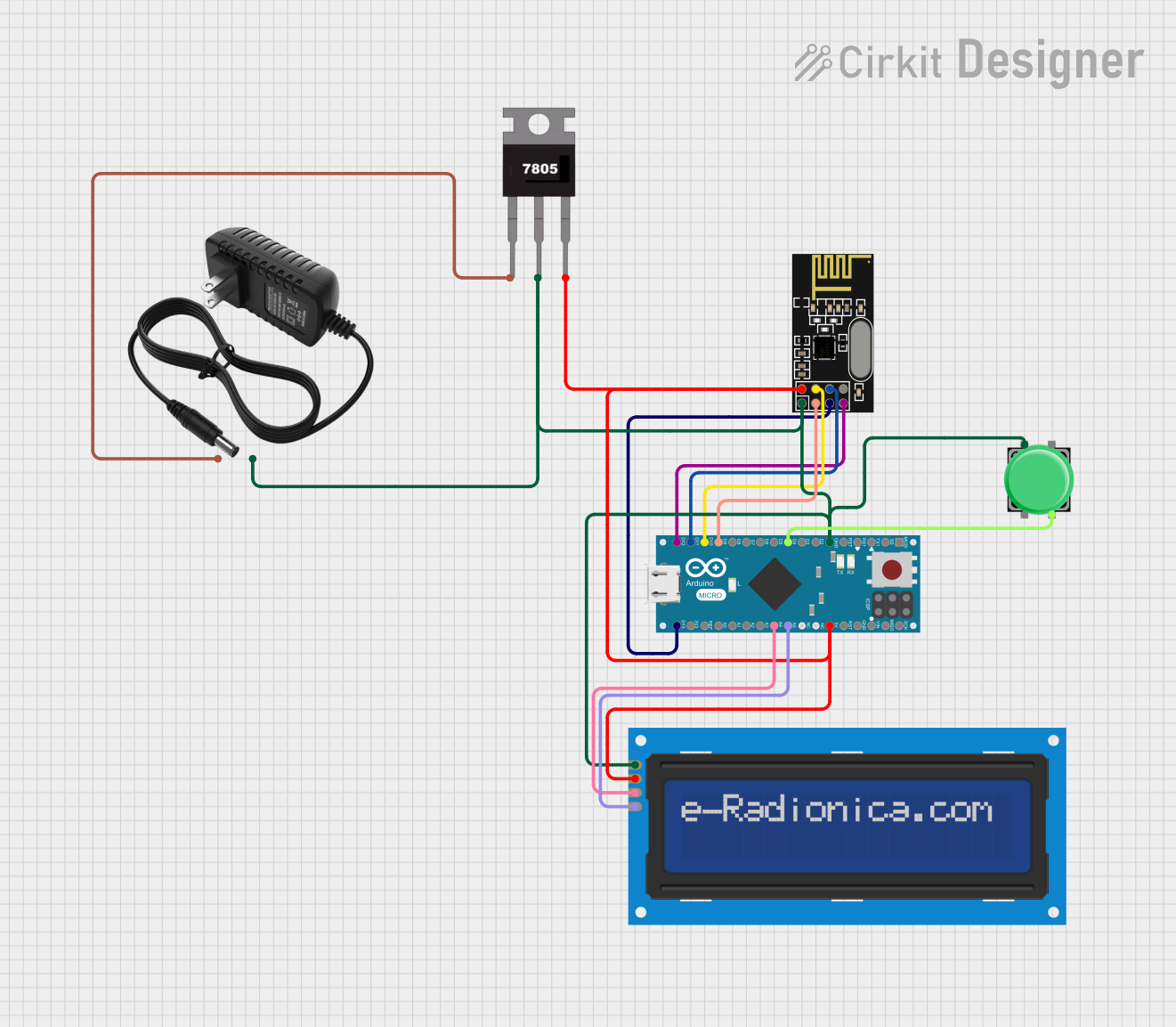
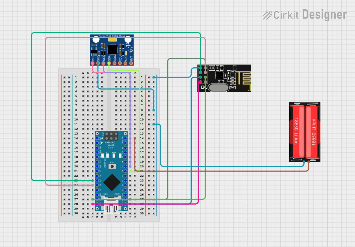
Explore Projects Built with Adafruit ItsyBitsy nRF52840
Common Applications and Use Cases
- Wearable electronics
- Wireless sensor networks
- IoT devices
- Smart home automation
- Prototyping for Bluetooth-enabled products
- Educational projects and learning platforms
Technical Specifications
Key Technical Details
- Microcontroller: Nordic nRF52840
- Processor: ARM Cortex-M4F 32-bit processor with floating-point unit (FPU)
- Clock Speed: 64 MHz
- Flash Memory: 1 MB
- SRAM: 256 KB
- I/O Pins: 23 GPIO pins
- Analog Inputs: 6 (14-bit ADC)
- PWM Outputs: All GPIO pins support PWM
- Voltage Supply: 3.3V regulator with 600mA peak current output
- USB: Native USB support with onboard USB bootloader and serial port debugging
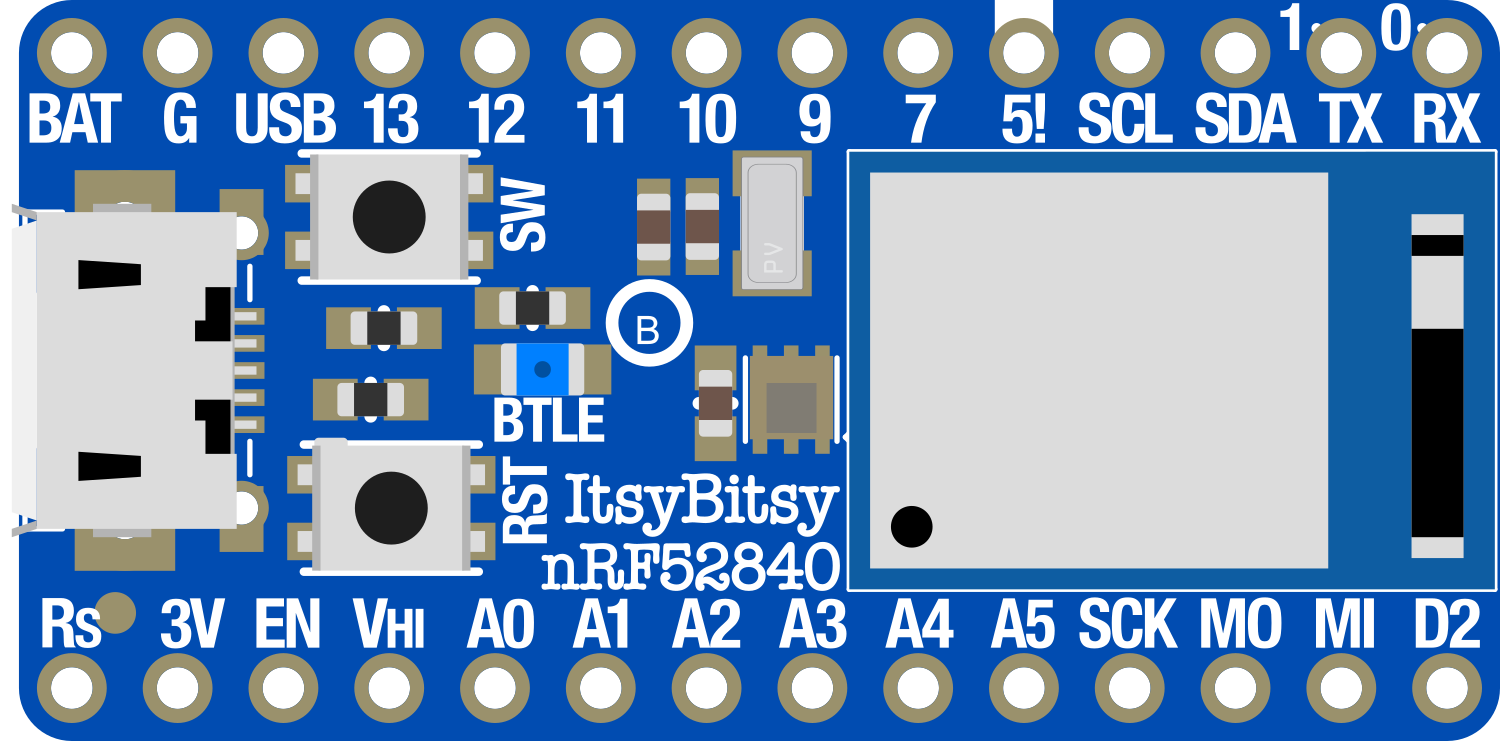
Pin Configuration and Descriptions
| Pin Number | Function | Description |
|---|---|---|
| 1 | GND | Ground |
| 2 | VBAT | Battery input for an optional LiPo battery |
| 3 | EN | Enable pin for the 3.3V regulator |
| 4 | VBUS | USB power input |
| 5 | 3V | 3.3V output from the regulator |
| 6-11 | A0-A5 | Analog input pins (can also be used as digital) |
| 12-28 | D0-D13, SCK, MO, MI | Digital I/O pins (D13 is also the LED pin) |
| 29 | RST | Reset pin |
| 30 | RX | UART receive pin |
| 31 | TX | UART transmit pin |
Usage Instructions
How to Use the Component in a Circuit
Powering the Board:
- Connect a 3.7V LiPo battery to the VBAT pin for battery operation.
- Alternatively, supply power via the USB port.
Programming the Board:
- Connect the board to a computer using a micro USB cable.
- Select the Adafruit ItsyBitsy nRF52840 board from your Arduino IDE or preferred development environment.
Connecting I/O:
- Use the GPIO pins for digital input and output.
- Analog pins A0-A5 can be used for analog sensors.
- PWM functionality is available on all GPIO pins for controlling motors or LEDs.
Important Considerations and Best Practices
- Always ensure that the power supply is within the specified range to prevent damage.
- When using the board with a battery, monitor the battery voltage to avoid deep discharge.
- Use appropriate pull-up or pull-down resistors with inputs to ensure defined logic levels.
- Avoid drawing more than the maximum current from the 3.3V regulator.
- When using BLE, follow best practices for wireless communication, such as proper antenna placement.
Troubleshooting and FAQs
Common Issues Users Might Face
Board not recognized by the computer:
- Ensure the micro USB cable is properly connected and the board is powered on.
- Try using a different USB port or cable.
Failure to upload sketches:
- Check that the correct board and port are selected in the development environment.
- Press the reset button twice quickly to enter bootloader mode if necessary.
Inconsistent behavior when running on battery:
- Verify that the battery is charged and functioning correctly.
- Check for proper connection at the VBAT pin.
Solutions and Tips for Troubleshooting
- Always start with simple blink sketches to ensure the board is functioning correctly.
- Use serial debugging to print out status and error messages.
- Consult the Adafruit forums and online resources for community support.
FAQs
Can I use the ItsyBitsy nRF52840 with Arduino IDE?
- Yes, you can program the board using the Arduino IDE by adding the Adafruit board support package.
Does the board support over-the-air (OTA) updates?
- Yes, the nRF52840 chipset supports OTA updates, which can be implemented using BLE.
What is the maximum range of the BLE on this board?
- The range depends on many factors, including antenna design and environmental conditions, but typically it can be up to 100 meters line-of-sight.
Example Code for Arduino UNO
Here is a simple example of how to blink the onboard LED using the Arduino IDE:
// Define the LED pin
#define LED_PIN 13

void setup() {
  // Set the LED pin as an output
  pinMode(LED_PIN, OUTPUT);
}

void loop() {
  // Turn the LED on
  digitalWrite(LED_PIN, HIGH);
  delay(500); // Wait for 500 milliseconds

  // Turn the LED off
  digitalWrite(LED_PIN, LOW);
  delay(500); // Wait for 500 milliseconds
}
Remember to select the Adafruit ItsyBitsy nRF52840 board from the board manager before uploading the code. This example will toggle the onboard LED every half-second, serving as a basic test to ensure your board is working correctly.