How to Use DAC: Examples, Pinouts, and Specs
Introduction
A Digital-to-Analog Converter (DAC) is an electronic device that converts digital data, typically binary, into an analog signal. This process is essential in bridging the gap between digital systems and the analog world. DACs are widely used in applications such as audio equipment (e.g., converting digital audio files into sound), video devices, signal processing, and instrumentation systems. They play a critical role in enabling digital devices to interact with real-world analog systems.
Common applications of DACs include:
- Audio playback systems (e.g., smartphones, music players, and amplifiers)
- Video signal generation (e.g., digital TVs and projectors)
- Data acquisition systems
- Control systems in industrial automation
- Signal generation in test and measurement equipment
Explore Projects Built with DAC
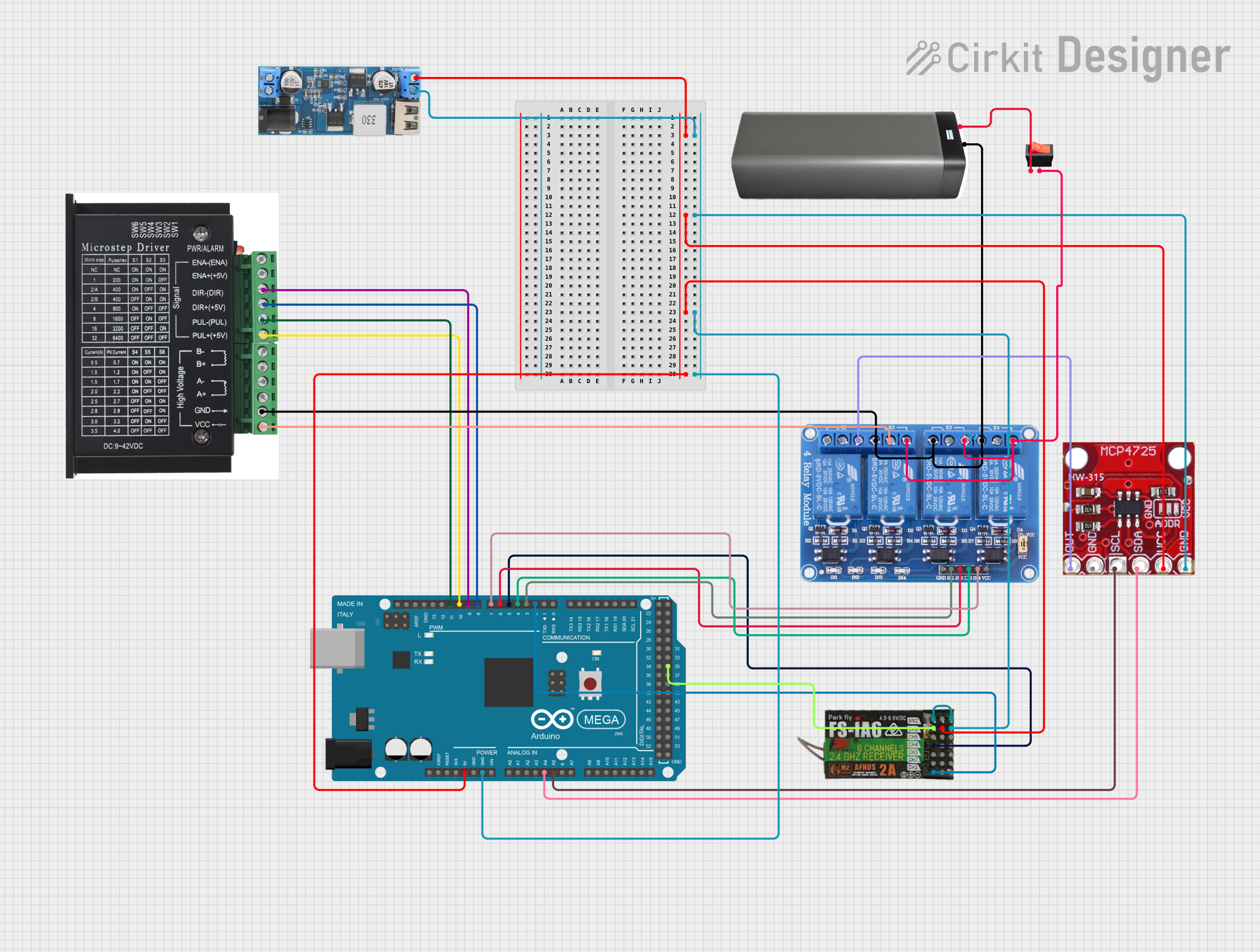

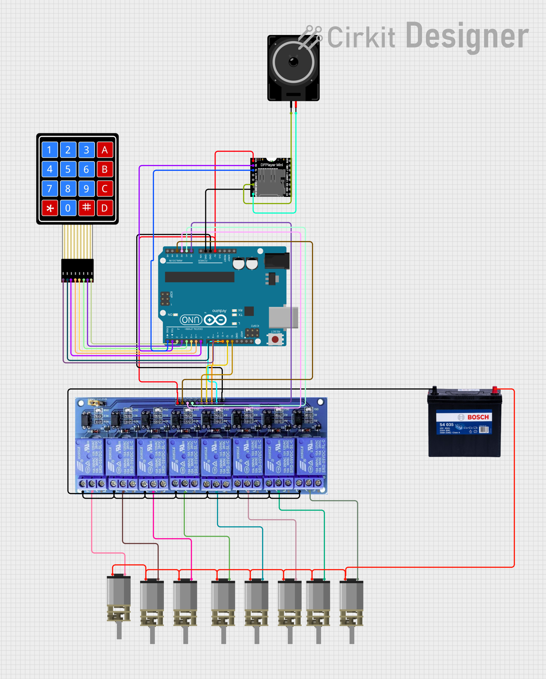
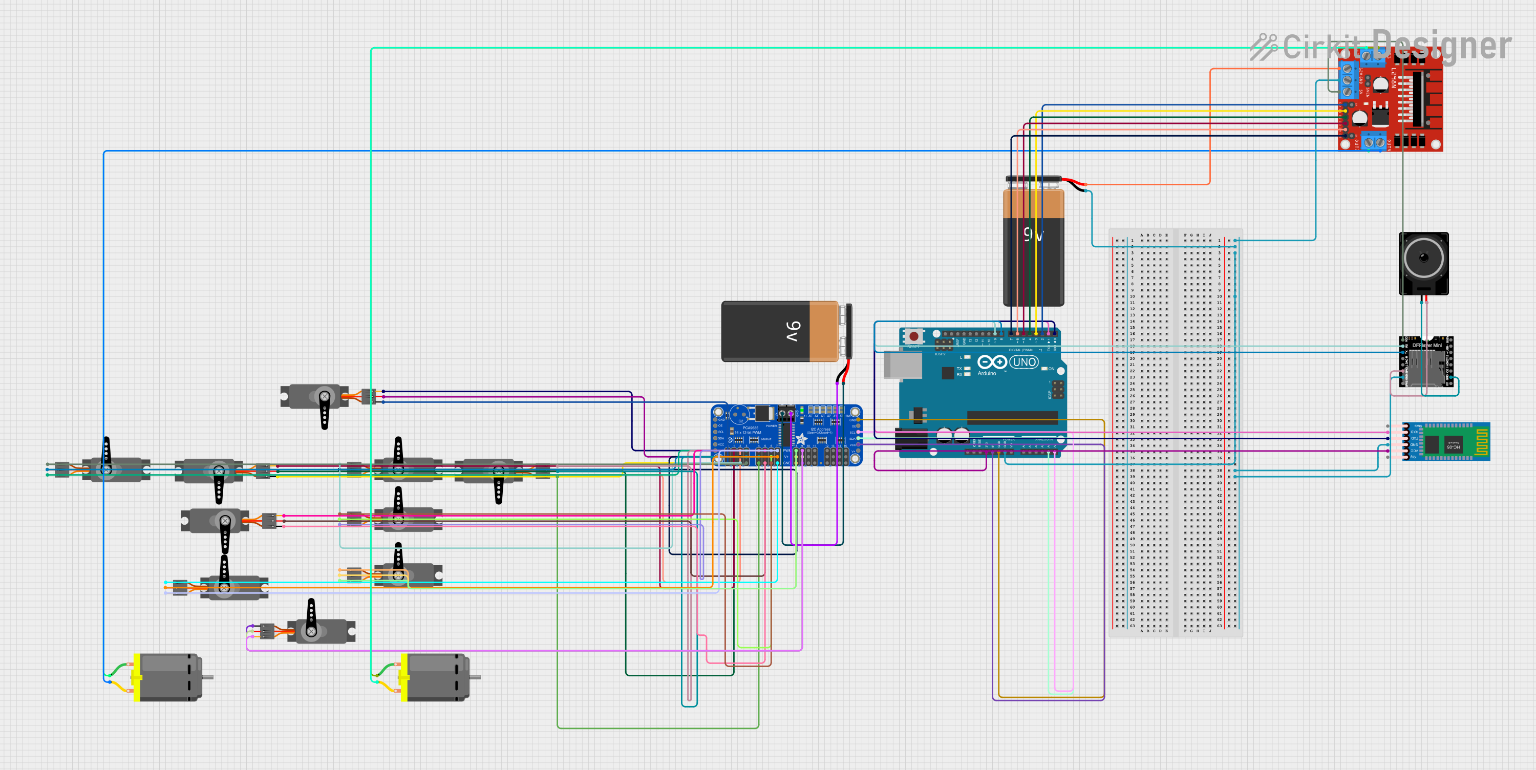
Explore Projects Built with DAC
Technical Specifications
Below are the general technical specifications for a typical DAC. Note that specific values may vary depending on the model and manufacturer.
Key Technical Details
- Resolution: 8-bit, 12-bit, 16-bit, or higher (determines output precision)
- Input Voltage Range: 0V to 5V (typical for low-power DACs)
- Output Voltage Range: 0V to reference voltage (e.g., 0V to 3.3V or 0V to 5V)
- Sampling Rate: Up to several MHz, depending on the application
- Power Supply Voltage: 3.3V or 5V (common for integrated DACs)
- Interface: Parallel, SPI, or I2C (depending on the DAC type)
- Output Type: Voltage or current output
Pin Configuration and Descriptions
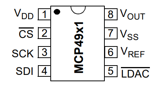
Below is an example pinout for a common 8-pin SPI DAC (e.g., MCP4921):
| Pin Number | Pin Name | Description |
|---|---|---|
| 1 | VDD | Positive power supply (e.g., 3.3V or 5V) |
| 2 | CS | Chip Select (active low) - used to enable communication with the DAC |
| 3 | SCK | Serial Clock - clock signal for SPI communication |
| 4 | SDI | Serial Data Input - used to send digital data to the DAC |
| 5 | LDAC | Load DAC (active low) - updates the DAC output when triggered |
| 6 | VOUT | Analog output - provides the converted analog signal |
| 7 | VREF | Reference voltage input - sets the maximum output voltage |
| 8 | GND | Ground connection |
Usage Instructions
How to Use the DAC in a Circuit
- Power the DAC: Connect the VDD pin to a suitable power supply (e.g., 3.3V or 5V) and the GND pin to ground.
- Set the Reference Voltage: Provide a stable reference voltage to the VREF pin. This voltage determines the maximum output range of the DAC.
- Connect the Output: Use the VOUT pin to retrieve the analog signal. This pin should be connected to the desired load or circuit.
- Interface with a Microcontroller: Use the appropriate communication protocol (e.g., SPI or I2C) to send digital data to the DAC. Ensure proper connections for the communication pins (e.g., CS, SCK, and SDI for SPI).
- Update the Output: Trigger the LDAC pin (if applicable) to update the analog output based on the received digital data.
Important Considerations and Best Practices
- Resolution: Choose a DAC with sufficient resolution for your application. Higher resolution provides finer control over the output signal.
- Reference Voltage: Use a stable and noise-free reference voltage to ensure accurate output.
- Output Load: Ensure the load connected to the VOUT pin does not exceed the DAC's drive capability.
- Decoupling Capacitors: Place decoupling capacitors near the power supply pins to reduce noise and improve stability.
- Communication Protocol: Verify the microcontroller's compatibility with the DAC's communication protocol (e.g., SPI or I2C).
Example Code for Arduino UNO
Below is an example of how to interface an MCP4921 SPI DAC with an Arduino UNO:
#include <SPI.h>

// Define SPI pins for the DAC
const int CS_PIN = 10; // Chip Select pin for the DAC

void setup() {
  pinMode(CS_PIN, OUTPUT); // Set CS pin as output
  digitalWrite(CS_PIN, HIGH); // Set CS pin high (inactive)

  SPI.begin(); // Initialize SPI communication
  SPI.setClockDivider(SPI_CLOCK_DIV2); // Set SPI clock speed
  SPI.setDataMode(SPI_MODE0); // Set SPI mode
}

void loop() {
  int digitalValue = 512; // Example digital value (10-bit resolution)

  // Convert digital value to analog using the DAC
  sendToDAC(digitalValue);

  delay(1000); // Wait for 1 second
}

void sendToDAC(int value) {
  // Ensure value is within 10-bit range (0 to 1023)
  value = constrain(value, 0, 1023);

  // Split the 10-bit value into two bytes
  byte highByte = (value >> 8) & 0x0F; // Upper 4 bits
  byte lowByte = value & 0xFF; // Lower 8 bits

  // Send data to the DAC
  digitalWrite(CS_PIN, LOW); // Activate the DAC
  SPI.transfer(highByte); // Send high byte
  SPI.transfer(lowByte); // Send low byte
  digitalWrite(CS_PIN, HIGH); // Deactivate the DAC
}
Troubleshooting and FAQs
Common Issues
No Output Signal:
- Ensure the DAC is powered correctly (check VDD and GND connections).
- Verify that the reference voltage (VREF) is stable and within the specified range.
- Check the communication protocol (e.g., SPI or I2C) for proper configuration.
Incorrect Output Voltage:
- Confirm that the digital data sent to the DAC matches the desired output.
- Verify the reference voltage and ensure it is noise-free.
- Check for excessive load on the VOUT pin.
Communication Errors:
- Ensure proper wiring of the communication pins (e.g., CS, SCK, and SDI for SPI).
- Verify that the microcontroller's SPI or I2C settings match the DAC's requirements.
FAQs
Q: Can I use a DAC with an Arduino UNO?
A: Yes, many DACs (e.g., MCP4921) are compatible with Arduino UNO. Use SPI or I2C libraries to communicate with the DAC.
Q: What resolution should I choose for my application?
A: The resolution depends on the precision required. For audio applications, 16-bit or higher is recommended, while 8-bit may suffice for simpler tasks.
Q: How do I ensure accurate output from the DAC?
A: Use a stable reference voltage, minimize noise in the circuit, and avoid exceeding the DAC's output drive capability.