How to Use NodeMcu-ESP32-C2: Examples, Pinouts, and Specs
Introduction
The NodeMcu-ESP32-C2, manufactured by Node, is a low-cost, open-source IoT platform based on the ESP8684 chip. It features integrated Wi-Fi and Bluetooth capabilities, making it an ideal choice for building connected devices and applications. This module is designed for developers and hobbyists looking to create smart home devices, IoT sensors, and other wireless communication projects.
Explore Projects Built with NodeMcu-ESP32-C2

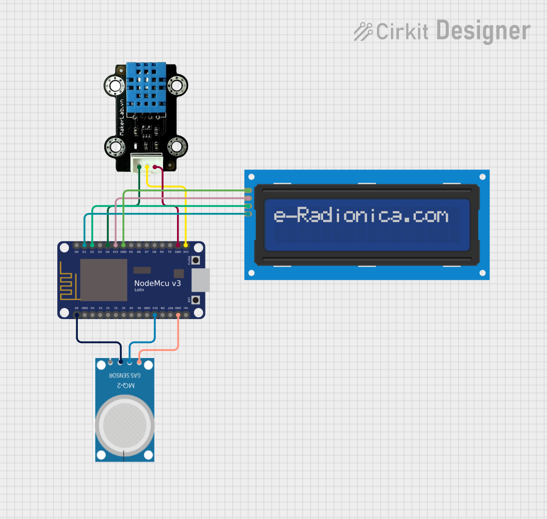
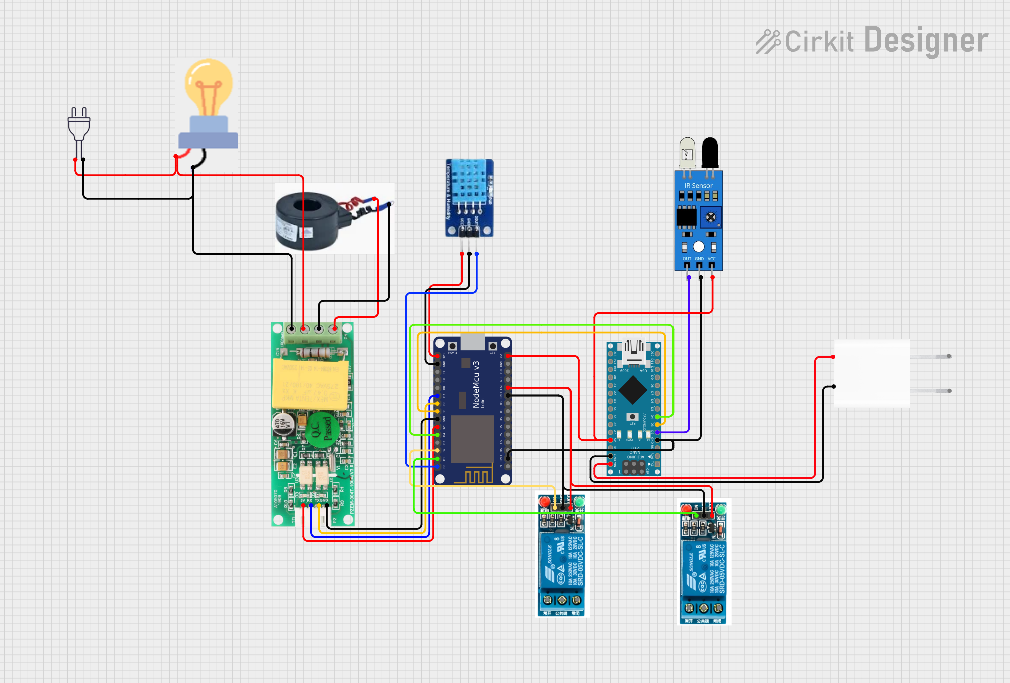
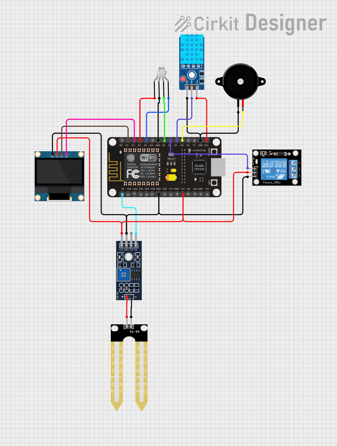
Explore Projects Built with NodeMcu-ESP32-C2
Common Applications and Use Cases
- Smart home automation systems
- IoT sensors and data loggers
- Wireless communication and control
- Wearable devices
- Prototyping and development of connected applications
Technical Specifications
The NodeMcu-ESP32-C2 is a compact and powerful module with the following key specifications:
| Parameter | Value |
|---|---|
| Manufacturer | Node |
| Part ID | ESP8684 |
| Microcontroller | ESP32-C2 (based on ESP8684) |
| Wireless Connectivity | Wi-Fi 4 (802.11 b/g/n), Bluetooth Low Energy (BLE) |
| Operating Voltage | 3.3V |
| Input Voltage Range | 5V (via USB) or 3.3V (via pin) |
| Flash Memory | 4 MB |
| SRAM | 272 KB |
| GPIO Pins | 18 |
| Communication Protocols | UART, SPI, I2C, PWM, ADC |
| Wi-Fi Frequency | 2.4 GHz |
| Power Consumption | Ultra-low power consumption in deep sleep mode |
| Dimensions | 18 mm x 25.5 mm |
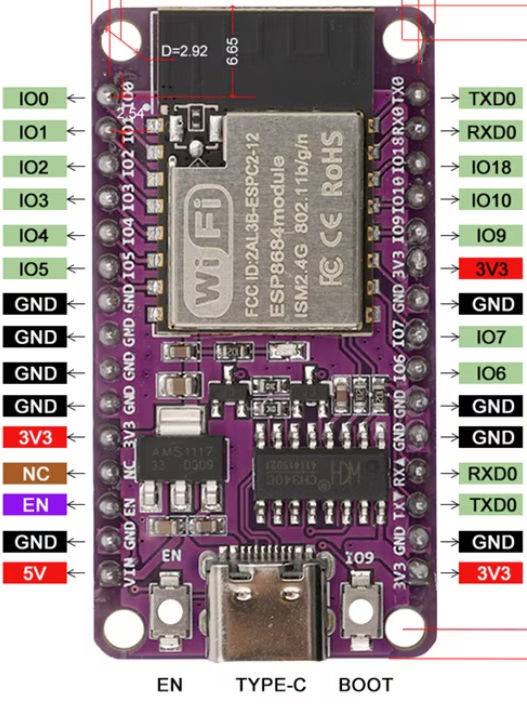
Pin Configuration and Descriptions
The NodeMcu-ESP32-C2 features a total of 18 GPIO pins, which can be configured for various functions. Below is the pinout description:
| Pin | Name | Function |
|---|---|---|
| 1 | GND | Ground |
| 2 | 3V3 | 3.3V power supply |
| 3 | EN | Enable pin (active high) |
| 4 | IO0 | GPIO0, can be used for input/output or boot mode selection |
| 5 | IO1 | GPIO1, UART TXD (default) |
| 6 | IO2 | GPIO2, UART RXD (default) |
| 7 | IO3 | GPIO3, general-purpose input/output |
| 8 | IO4 | GPIO4, supports PWM, ADC, or digital I/O |
| 9 | IO5 | GPIO5, supports PWM, ADC, or digital I/O |
| 10 | IO6 | GPIO6, SPI CLK (default) |
| 11 | IO7 | GPIO7, SPI MOSI (default) |
| 12 | IO8 | GPIO8, SPI MISO (default) |
| 13 | IO9 | GPIO9, general-purpose input/output |
| 14 | IO10 | GPIO10, general-purpose input/output |
| 15 | IO11 | GPIO11, general-purpose input/output |
| 16 | IO12 | GPIO12, general-purpose input/output |
| 17 | IO13 | GPIO13, general-purpose input/output |
| 18 | RST | Reset pin |
Usage Instructions
How to Use the NodeMcu-ESP32-C2 in a Circuit
Powering the Module:
- Use a 5V USB connection or supply 3.3V directly to the 3V3 pin.
- Ensure the ground (GND) pin is connected to the circuit's ground.
Programming the Module:
- The NodeMcu-ESP32-C2 can be programmed using the Arduino IDE or the ESP-IDF framework.
- Install the necessary board support package (BSP) for ESP32-C2 in the Arduino IDE.
Connecting Peripherals:
- Use the GPIO pins for connecting sensors, actuators, or other peripherals.
- Configure the pins in your code for the desired functionality (e.g., input, output, PWM).
Uploading Code:
- Connect the module to your computer via USB.
- Select the correct board and port in the Arduino IDE.
- Upload your code to the module.
Important Considerations and Best Practices
- Voltage Levels: Ensure all connected peripherals operate at 3.3V logic levels to avoid damaging the module.
- Deep Sleep Mode: Use deep sleep mode to minimize power consumption in battery-powered applications.
- Antenna Placement: Avoid placing metal objects near the onboard antenna to ensure optimal Wi-Fi and Bluetooth performance.
- Boot Mode: To enter bootloader mode, hold the IO0 pin low while resetting the module.
Example Code for Arduino UNO Integration
Below is an example of how to blink an LED connected to GPIO4:
// Define the GPIO pin for the LED
#define LED_PIN 4

void setup() {
  // Set the LED pin as an output
  pinMode(LED_PIN, OUTPUT);
}

void loop() {
  // Turn the LED on
  digitalWrite(LED_PIN, HIGH);
  delay(1000); // Wait for 1 second

  // Turn the LED off
  digitalWrite(LED_PIN, LOW);
  delay(1000); // Wait for 1 second
}
Troubleshooting and FAQs
Common Issues and Solutions
Module Not Detected by Computer:
- Ensure the USB cable is functional and supports data transfer.
- Install the correct USB-to-serial driver for the NodeMcu-ESP32-C2.
Code Upload Fails:
- Check that the correct board and port are selected in the Arduino IDE.
- Ensure the module is in bootloader mode by holding IO0 low during reset.
Wi-Fi Connection Issues:
- Verify the SSID and password in your code.
- Ensure the module is within range of the Wi-Fi router.
Overheating:
- Check for short circuits or excessive current draw from connected peripherals.
FAQs
Q: Can the NodeMcu-ESP32-C2 operate on 5V logic?
A: No, the module operates on 3.3V logic. Use level shifters if interfacing with 5V devices.
Q: How do I reset the module?
A: Press the RST pin or the onboard reset button to reset the module.
Q: Can I use the module for Bluetooth communication?
A: Yes, the NodeMcu-ESP32-C2 supports Bluetooth Low Energy (BLE) for wireless communication.
Q: What is the maximum Wi-Fi range?
A: The range depends on environmental factors but typically extends up to 50 meters indoors and 200 meters outdoors.