
How to Use AC110-245V to DC12V 6A 70W Power Supply module board: Examples, Pinouts, and Specs
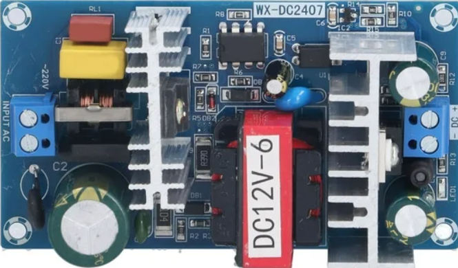
 Design with AC110-245V to DC12V 6A 70W Power Supply module board in Cirkit Designer
Introduction
The AC110-245V to DC12V 6A Power Supply Module (Manufacturer Part ID: WX-DC2407) is a compact and efficient power supply solution designed to convert high-voltage alternating current (AC) input (110-245V) into a stable 12V direct current (DC) output. With a maximum current capacity of 6A and a power output of 70W, this module is ideal for powering a wide range of electronic devices, including LED strips, surveillance cameras, and small appliances.
Explore Projects Built with AC110-245V to DC12V 6A 70W Power Supply module board
 Open Project in Cirkit Designer
 Open Project in Cirkit Designer
 Open Project in Cirkit Designer
 Open Project in Cirkit Designer
Explore Projects Built with AC110-245V to DC12V 6A 70W Power Supply module board
Open Project in Cirkit DesignerOpen Project in Cirkit DesignerOpen Project in Cirkit DesignerOpen Project in Cirkit DesignerCommon Applications and Use Cases
- Powering LED lighting systems, such as LED strips or panels.
- Supplying power to CCTV cameras and other security systems.
- Driving small DC motors or actuators in automation projects.
- Providing a stable 12V DC source for DIY electronics and prototyping.
- Replacing bulky traditional transformers in compact designs.
Technical Specifications
The following table outlines the key technical details of the module:
| Parameter | Specification |
|---|---|
| Input Voltage Range | AC 110V - 245V |
| Output Voltage | DC 12V |
| Maximum Output Current | 6A |
| Maximum Power Output | 70W |
| Efficiency | ≥85% |
| Operating Temperature | -20°C to +60°C |
| Dimensions | 85mm x 58mm x 33mm |
| Weight | ~120g |
| Protection Features | Overload, Overvoltage, Short Circuit |
Pin Configuration and Descriptions
The module has clearly labeled input and output terminals for easy integration into circuits. The table below describes the terminal connections:
| Terminal Label | Description |
|---|---|
| L | Live AC input (110-245V) |
| N | Neutral AC input |
| GND | Ground connection for DC output |
| +12V | Positive 12V DC output |
Usage Instructions
How to Use the Component in a Circuit
- Safety First: Ensure the module is powered off and disconnected from any power source before wiring.
- Connect the AC Input:
- Connect the live AC wire to the terminal labeled
L. - Connect the neutral AC wire to the terminal labeled
N.
- Connect the live AC wire to the terminal labeled
- Connect the DC Output:
- Connect the positive wire of your load to the
+12Vterminal. - Connect the ground wire of your load to the
GNDterminal.
- Connect the positive wire of your load to the
- Secure Connections: Double-check all connections to ensure they are secure and free of loose wires.
- Power On: Once all connections are verified, connect the AC input to the power source and switch it on.
Important Considerations and Best Practices
- Load Compatibility: Ensure the connected load does not exceed the maximum power output of 70W or the current limit of 6A.
- Ventilation: Install the module in a well-ventilated area to prevent overheating.
- Insulation: Avoid exposing the module to moisture or conductive materials to prevent short circuits.
- Fuse Protection: Consider adding a fuse on the AC input side for additional safety.
- Polarity: Always observe correct polarity when connecting the DC output to your load.
Example: Using with an Arduino UNO
This module can be used to power an Arduino UNO and other peripherals. Below is an example of how to connect the module to an Arduino UNO:
- Connect the
+12Vterminal of the module to the VIN pin of the Arduino UNO. - Connect the
GNDterminal of the module to the GND pin of the Arduino UNO. - Ensure the total current draw of the Arduino and connected peripherals does not exceed 6A.
Sample Arduino Code
// Example code to blink an LED connected to pin 13 of the Arduino UNO
// Ensure the Arduino is powered via the 12V power supply module

void setup() {
  pinMode(13, OUTPUT); // Set pin 13 as an output
}

void loop() {
  digitalWrite(13, HIGH); // Turn the LED on
  delay(1000);            // Wait for 1 second
  digitalWrite(13, LOW);  // Turn the LED off
  delay(1000);            // Wait for 1 second
}
Troubleshooting and FAQs
Common Issues Users Might Face
No Output Voltage:
- Cause: Loose or incorrect wiring.
- Solution: Verify all connections, especially the AC input terminals (
LandN).
Overheating:
- Cause: Insufficient ventilation or excessive load.
- Solution: Ensure the module is installed in a well-ventilated area and reduce the load if necessary.
Output Voltage Fluctuations:
- Cause: Unstable AC input or exceeding the power rating.
- Solution: Check the AC input voltage and ensure the load does not exceed 70W.
Short Circuit Protection Triggered:
- Cause: A short circuit in the connected load.
- Solution: Inspect the load for wiring issues and resolve the short circuit.
FAQs
Q1: Can this module be used outdoors?
A1: No, the module is not waterproof. It should be used in a dry, indoor environment.
Q2: Can I use this module to charge a 12V battery?
A2: This module is not designed for battery charging as it lacks current regulation features required for safe charging.
Q3: What happens if the input voltage exceeds 245V?
A3: The module may get damaged. Always ensure the input voltage stays within the specified range of 110-245V AC.
Q4: Is it safe to use this module with inductive loads like motors?
A4: Yes, but ensure the load does not exceed the module's power and current ratings. For high inrush currents, additional protection may be required.
By following this documentation, users can safely and effectively integrate the AC110-245V to DC12V 6A Power Supply Module into their projects.