
How to Use LED: Two Pin (red) - Long Pins: Examples, Pinouts, and Specs
 Design with LED: Two Pin (red) - Long Pins in Cirkit Designer
Introduction
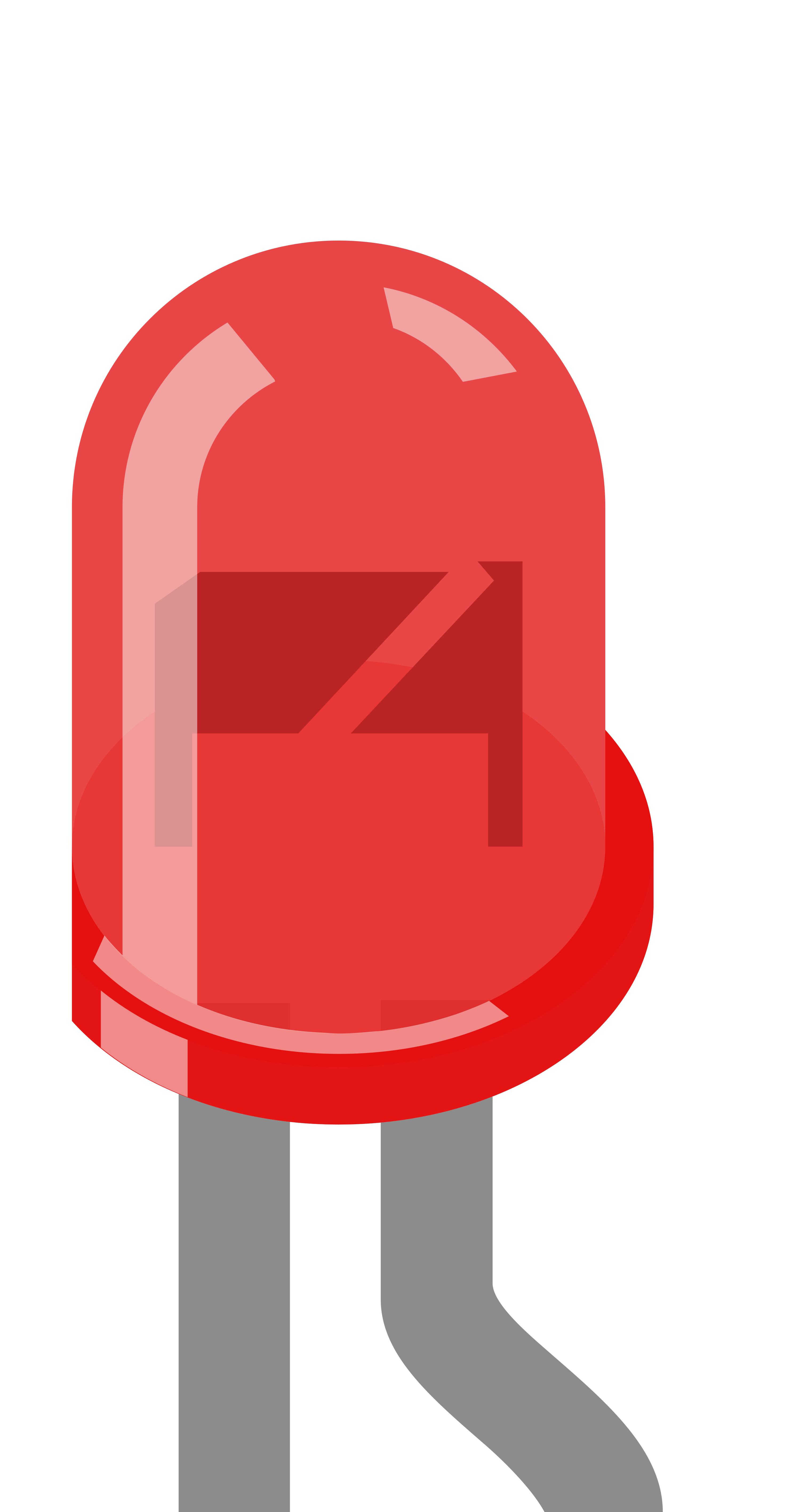
A Light Emitting Diode (LED) is a semiconductor device that emits light when an electric current flows through it. This specific LED emits red light and features two pins of differing lengths: the longer pin is the anode (positive), and the shorter pin is the cathode (negative). This design ensures proper orientation during circuit assembly.
Common applications for this red LED include:
- Indicator lights in electronic devices
- Status indicators in circuits
- Decorative lighting
- Educational and prototyping projects
Explore Projects Built with LED: Two Pin (red) - Long Pins
 Open Project in Cirkit Designer
 Open Project in Cirkit Designer
 Open Project in Cirkit Designer
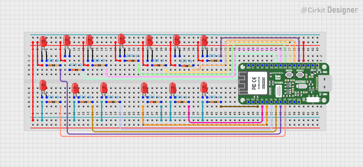 Open Project in Cirkit Designer
Explore Projects Built with LED: Two Pin (red) - Long Pins
Open Project in Cirkit DesignerOpen Project in Cirkit DesignerOpen Project in Cirkit DesignerOpen Project in Cirkit DesignerTechnical Specifications
Below are the key technical details for the red two-pin LED:
| Parameter | Value |
|---|---|
| Forward Voltage (Vf) | 1.8V to 2.2V |
| Forward Current (If) | 20mA (typical) |
| Maximum Current (Imax) | 30mA |
| Reverse Voltage (Vr) | 5V (maximum) |
| Wavelength | 620nm to 630nm (red light) |
| Viewing Angle | 20° to 30° |
| Operating Temperature | -40°C to +85°C |
Pin Configuration
The LED has two pins, as described below:
| Pin Name | Pin Description | Identification Method |
|---|---|---|
| Anode | Positive terminal | Longer pin |
| Cathode | Negative terminal | Shorter pin, flat edge on body |
Usage Instructions
How to Use the LED in a Circuit
Determine Polarity: Identify the anode (longer pin) and cathode (shorter pin or flat edge on the LED body).
Connect to Power Source:
- Connect the anode to the positive terminal of the power source.
- Connect the cathode to the negative terminal.
Use a Current-Limiting Resistor: To prevent damage, always use a resistor in series with the LED. Calculate the resistor value using Ohm's Law: [ R = \frac{V_{supply} - V_f}{I_f} ] Where:
- ( V_{supply} ) is the supply voltage.
- ( V_f ) is the forward voltage of the LED (1.8V to 2.2V).
- ( I_f ) is the forward current (20mA or 0.02A).
For example, with a 5V supply: [ R = \frac{5V - 2V}{0.02A} = 150\Omega ]
Test the LED: Once connected, the LED should emit red light when powered.
Important Considerations and Best Practices
- Polarity Matters: Reversing the polarity can damage the LED.
- Avoid Overcurrent: Exceeding the maximum current (30mA) can permanently damage the LED.
- Use Proper Resistors: Always calculate and use the correct resistor value to limit current.
- Heat Management: While LEDs generate minimal heat, ensure proper ventilation in high-density circuits.
Example: Connecting the LED to an Arduino UNO
Below is an example of how to connect and control the LED using an Arduino UNO:
Circuit Setup
- Connect the anode (long pin) of the LED to a digital pin on the Arduino (e.g., pin 13) through a 220Ω resistor.
- Connect the cathode (short pin) to the Arduino's GND pin.
Arduino Code
// Define the pin connected to the LED
const int ledPin = 13;

void setup() {
  // Set the LED pin as an output
  pinMode(ledPin, OUTPUT);
}

void loop() {
  // Turn the LED on
  digitalWrite(ledPin, HIGH);
  delay(1000); // Wait for 1 second

  // Turn the LED off
  digitalWrite(ledPin, LOW);
  delay(1000); // Wait for 1 second
}
Troubleshooting and FAQs
Common Issues
LED Does Not Light Up:
Cause: Incorrect polarity.
Solution: Ensure the anode is connected to the positive terminal and the cathode to the negative terminal.
Cause: No current-limiting resistor or incorrect resistor value.
Solution: Verify the resistor value and connections.
LED Flickers or is Dim:
- Cause: Insufficient current or loose connections.
- Solution: Check the power supply and ensure all connections are secure.
LED Burns Out Quickly:
- Cause: Excessive current.
- Solution: Use a resistor to limit the current to 20mA.
FAQs
Q: Can I connect the LED directly to a 5V power source without a resistor?
A: No, doing so will likely damage the LED due to excessive current. Always use a current-limiting resistor.
Q: How do I know if the LED is damaged?
A: A damaged LED will not emit light even when connected correctly. Test with a multimeter in diode mode to confirm.
Q: Can I use this LED with a 3.3V power source?
A: Yes, but you still need a resistor to limit the current. Calculate the resistor value based on the supply voltage and forward voltage.
This documentation provides all the necessary details to use the red two-pin LED effectively in your projects.