How to Use Servo 8120MG front: Examples, Pinouts, and Specs

Introduction
The Servo 8120MG is a high-torque, metal gear servo designed for precise control in robotics, remote-controlled (RC) vehicles, and other motion control applications. Its robust construction, featuring durable metal gears, ensures long-lasting performance even under demanding conditions. With a wide range of motion and reliable operation, the Servo 8120MG is ideal for projects requiring accurate positioning and high torque.
Explore Projects Built with Servo 8120MG front


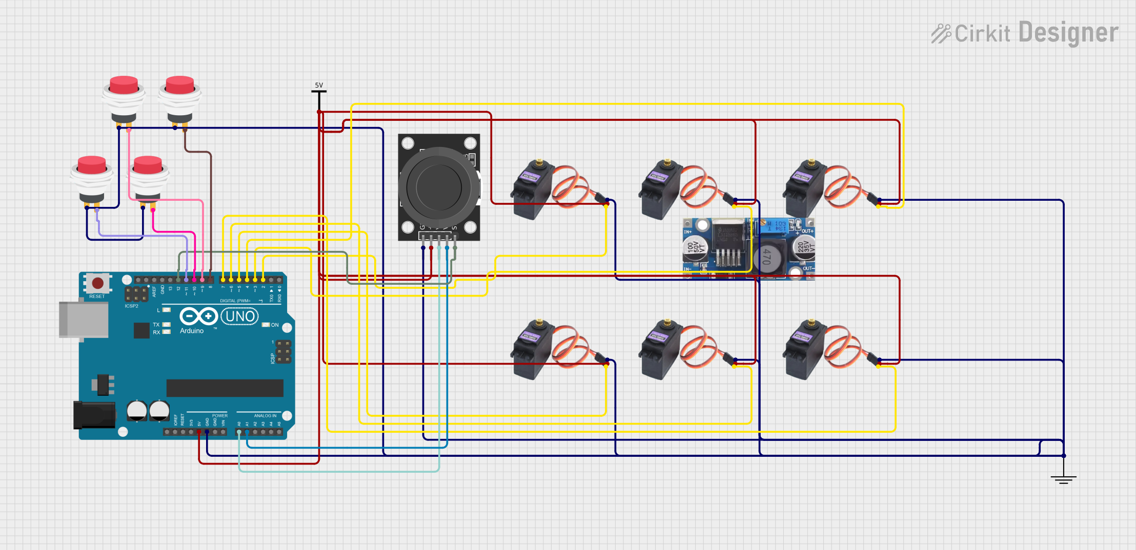
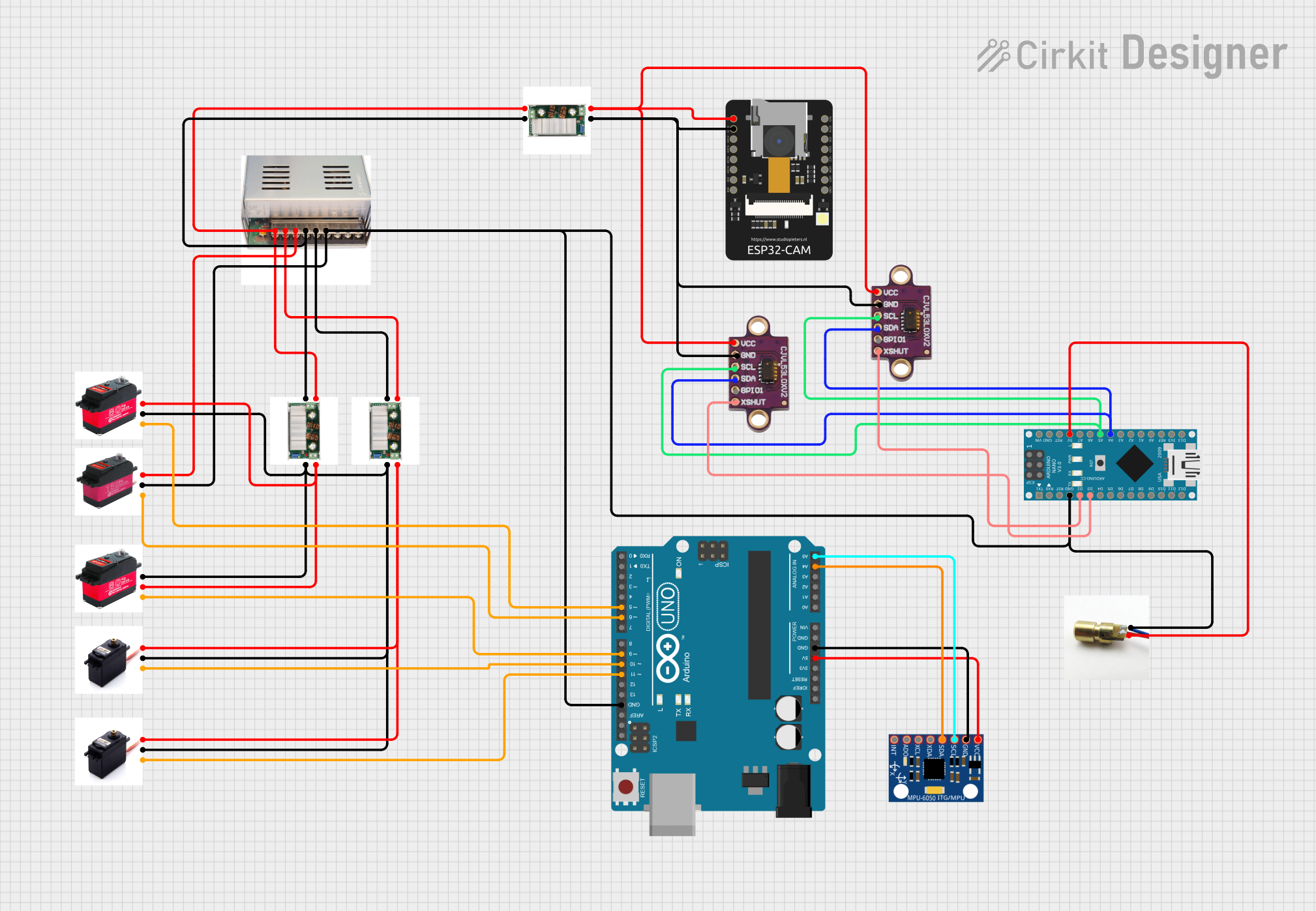
Explore Projects Built with Servo 8120MG front
Common Applications
- Robotics (e.g., robotic arms, grippers, and humanoid robots)
- Remote-controlled vehicles (e.g., cars, boats, and planes)
- Automated systems (e.g., pan-tilt camera mounts)
- DIY projects requiring precise motion control
Technical Specifications
The Servo 8120MG is designed to deliver high performance and reliability. Below are its key technical details:
| Parameter | Specification |
|---|---|
| Operating Voltage | 4.8V to 6.6V |
| Stall Torque | 12 kg·cm (at 4.8V), 14 kg·cm (at 6.6V) |
| Operating Speed | 0.18 sec/60° (at 4.8V), 0.16 sec/60° (at 6.6V) |
| Gear Type | Metal |
| Control Signal | PWM (Pulse Width Modulation) |
| PWM Pulse Range | 500 µs to 2500 µs |
| Angle Range | 0° to 180° |
| Connector Type | 3-pin female header (standard servo connector) |
| Dimensions | 40.5 mm x 20.2 mm x 38 mm |
| Weight | 55 g |
Pin Configuration
The Servo 8120MG has a standard 3-pin connector. Below is the pinout description:
| Pin | Wire Color | Function |
|---|---|---|
| 1 | Brown | Ground (GND) |
| 2 | Red | Power (VCC) |
| 3 | Orange | Signal (PWM Input) |
Usage Instructions
How to Use the Servo 8120MG in a Circuit
- Power Supply: Connect the red wire to a power source (4.8V to 6.6V) and the brown wire to ground. Ensure the power supply can provide sufficient current (at least 2A) to handle the servo's peak load.
- Signal Input: Connect the orange wire to a PWM-capable pin on your microcontroller (e.g., Arduino, Raspberry Pi). The PWM signal controls the servo's position.
- PWM Signal: Use a PWM signal with a pulse width between 500 µs (0°) and 2500 µs (180°). A pulse width of 1500 µs corresponds to the neutral position (90°).
Important Considerations
- Power Requirements: Use a separate power supply for the servo if your microcontroller cannot provide sufficient current.
- Avoid Overloading: Do not exceed the torque rating to prevent damage to the gears or motor.
- Signal Stability: Ensure the PWM signal is stable to avoid erratic movements.
- Mounting: Secure the servo properly to prevent vibrations or misalignment during operation.
Example Code for Arduino UNO
Below is an example of how to control the Servo 8120MG using an Arduino UNO:
#include <Servo.h> // Include the Servo library

Servo myServo; // Create a Servo object

void setup() {
  myServo.attach(9); // Attach the servo to pin 9 on the Arduino
}

void loop() {
  myServo.write(0); // Move the servo to 0 degrees
  delay(1000); // Wait for 1 second

  myServo.write(90); // Move the servo to 90 degrees
  delay(1000); // Wait for 1 second

  myServo.write(180); // Move the servo to 180 degrees
  delay(1000); // Wait for 1 second
}
Best Practices
- Use a capacitor across the power supply to smooth voltage fluctuations.
- Avoid running the servo continuously at its maximum torque to extend its lifespan.
- Test the servo with a low load before integrating it into your project.
Troubleshooting and FAQs
Common Issues and Solutions
Servo Not Moving:
- Cause: Incorrect wiring or insufficient power supply.
- Solution: Double-check the wiring and ensure the power supply meets the voltage and current requirements.
Erratic Movements:
- Cause: Unstable PWM signal or electrical noise.
- Solution: Use a decoupling capacitor near the servo and ensure the PWM signal is clean.
Overheating:
- Cause: Prolonged operation at high torque or insufficient ventilation.
- Solution: Reduce the load on the servo and ensure proper airflow around it.
Limited Range of Motion:
- Cause: Incorrect PWM signal range.
- Solution: Verify that the PWM pulse width is within the specified range (500 µs to 2500 µs).
FAQs
Q: Can I use the Servo 8120MG with a 3.3V microcontroller?
A: Yes, but you must use a level shifter or ensure the PWM signal is compatible with the servo's input requirements.
Q: What is the maximum current draw of the Servo 8120MG?
A: The maximum current draw can reach up to 2A under heavy load. Ensure your power supply can handle this.
Q: Can the Servo 8120MG rotate continuously?
A: No, this is a standard servo with a range of motion limited to 0° to 180°. For continuous rotation, use a continuous rotation servo.
Q: How do I calibrate the servo's neutral position?
A: Send a 1500 µs PWM signal to the servo and adjust the mounting position of the servo horn if necessary.
By following this documentation, you can effectively integrate the Servo 8120MG into your projects and troubleshoot common issues.