How to Use GPIO Expaander: Examples, Pinouts, and Specs
Introduction
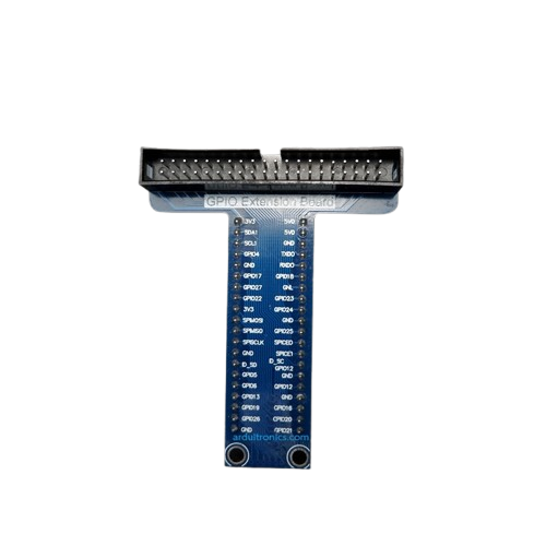
A GPIO (General Purpose Input/Output) Expander is an electronic component that increases the number of GPIO pins available for use with a microcontroller or other digital systems. This is particularly useful when the number of built-in GPIO pins is insufficient for a project's needs. GPIO Expanders are commonly used in applications such as interfacing with multiple sensors, driving a large number of LEDs, or expanding the connectivity of microcontrollers like the Arduino UNO.
Explore Projects Built with GPIO Expaander


Explore Projects Built with GPIO Expaander
Technical Specifications
Key Technical Details
- Voltage: Typically 1.8V to 5.5V, but refer to the specific expander's datasheet.
- Current: Maximum source/sink current per pin varies by model.
- Power Ratings: Dependent on the operating voltage and current per pin.
- Communication Interface: I2C, SPI, or other serial communication protocols.
- Number of Expandable Pins: Varies by model (e.g., 8, 16, 32 additional GPIO pins).
Pin Configuration and Descriptions
| Pin Number | Name | Description |
|---|---|---|
| 1 | VDD | Power supply voltage |
| 2 | GND | Ground connection |
| 3 | SCL | Serial clock line (I2C) |
| 4 | SDA | Serial data line (I2C) |
| 5-n | IO0-IOx | Input/Output pins (x depends on the model) |
| n+1 | INT | Interrupt output (optional) |
| n+2 | RST | Reset pin (optional) |
Note: The above table is a generic representation. Refer to the specific GPIO Expander datasheet for exact pin configurations.
Usage Instructions
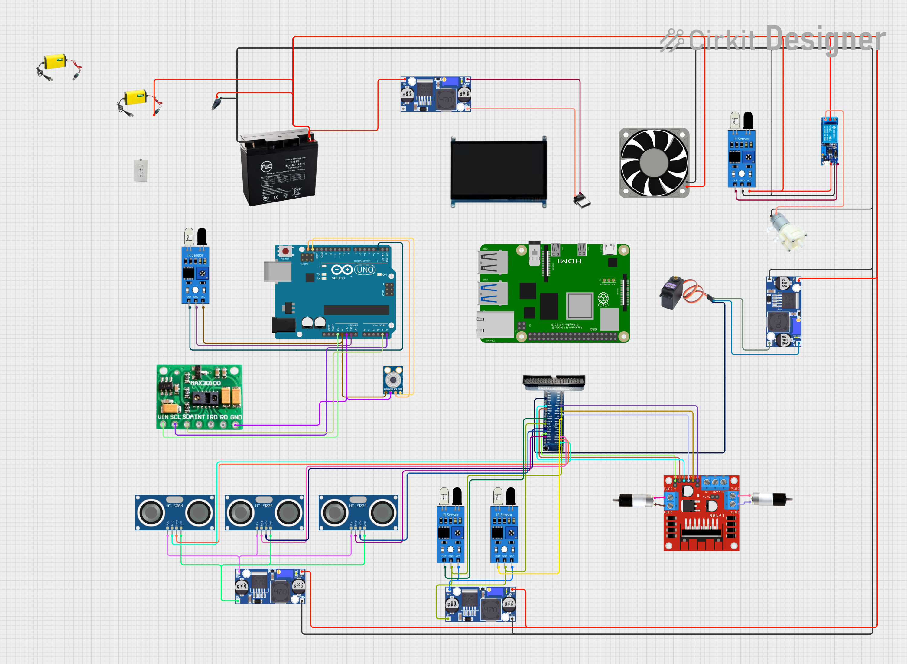
How to Use the Component in a Circuit
- Power Connections: Connect the VDD pin to the power supply and the GND pin to the ground.
- Communication Lines: Connect the SCL and SDA pins to the corresponding SCL and SDA pins on the microcontroller for I2C communication.
- I/O Pins: Connect the IO pins to the external devices or sensors as required.
- Interrupts (Optional): If available, the INT pin can be connected to an interrupt-capable GPIO pin on the microcontroller to handle events.
- Reset (Optional): The RST pin can be connected to a GPIO pin or left unconnected if not used.
Important Considerations and Best Practices
- Ensure that the power supply voltage matches the voltage rating of the GPIO Expander.
- Use pull-up resistors on the SCL and SDA lines if they are not built into the microcontroller.
- Configure the GPIO Expander's registers according to the desired pin direction (input or output) and functionality.
- Avoid exceeding the maximum current rating for each IO pin to prevent damage to the device.
Example Code for Arduino UNO
#include <Wire.h> // Include the I2C library

// Define the I2C address for the GPIO Expander (check datasheet)
#define GPIO_EXPANDER_ADDRESS 0x20

void setup() {
  Wire.begin(); // Initialize I2C communication
  // Configure pins as outputs (replace with actual configuration code)
  // This is a placeholder and will vary depending on the expander model
  writeGPIOExpander(GPIO_EXPANDER_ADDRESS, 0xFF); // Set all pins as outputs
}

void loop() {
  // Example: Toggle all pins
  writeGPIOExpander(GPIO_EXPANDER_ADDRESS, 0x00); // Set all pins LOW
  delay(500);
  writeGPIOExpander(GPIO_EXPANDER_ADDRESS, 0xFF); // Set all pins HIGH
  delay(500);
}

// Function to write to the GPIO Expander
void writeGPIOExpander(byte address, byte data) {
  Wire.beginTransmission(address);
  Wire.write(data); // Send data byte
  Wire.endTransmission(); // Stop transmitting
}
Note: The above code is a simplified example. The actual implementation will depend on the specific GPIO Expander model and its register map.
Troubleshooting and FAQs
Common Issues
- I2C Communication Failure: Ensure that the SCL and SDA lines are connected correctly and that pull-up resistors are in place if needed.
- Incorrect Pin States: Verify that the GPIO Expander's registers are configured correctly for the desired pin states (input/output).
- Insufficient Power Supply: Make sure that the power supply can deliver sufficient current for all connected devices.
Solutions and Tips for Troubleshooting
- Use a multimeter to check for proper voltage levels at the VDD and GND pins.
- Use an oscilloscope or logic analyzer to monitor the SCL and SDA lines for proper communication.
- Check for soldering issues or loose connections that may affect the functionality of the GPIO Expander.
FAQs
Q: Can I use multiple GPIO Expanders with a single microcontroller? A: Yes, as long as they have different I2C addresses or you are using chip select lines for SPI models.
Q: How do I change the I2C address of the GPIO Expander? A: Some GPIO Expanders have address pins that can be connected to VDD or GND to set different addresses. Check the datasheet for details.
Q: What is the maximum number of IO pins I can expand to? A: This depends on the number of GPIO Expanders you can connect to your microcontroller and their individual pin counts. Ensure that the microcontroller can handle the communication load.
Remember to always refer to the specific GPIO Expander's datasheet for accurate information regarding operation, limitations, and capabilities.