How to Use Security Door Lock System: Examples, Pinouts, and Specs
Introduction
The SYD Security Door Lock System is an advanced electronic locking mechanism designed to enhance the security of residential, commercial, and industrial properties. This system integrates modern access control technologies, such as keypads, RFID readers, and biometric scanners, to prevent unauthorized access. It is a reliable and versatile solution for securing doors, offering both convenience and robust protection.
Explore Projects Built with Security Door Lock System
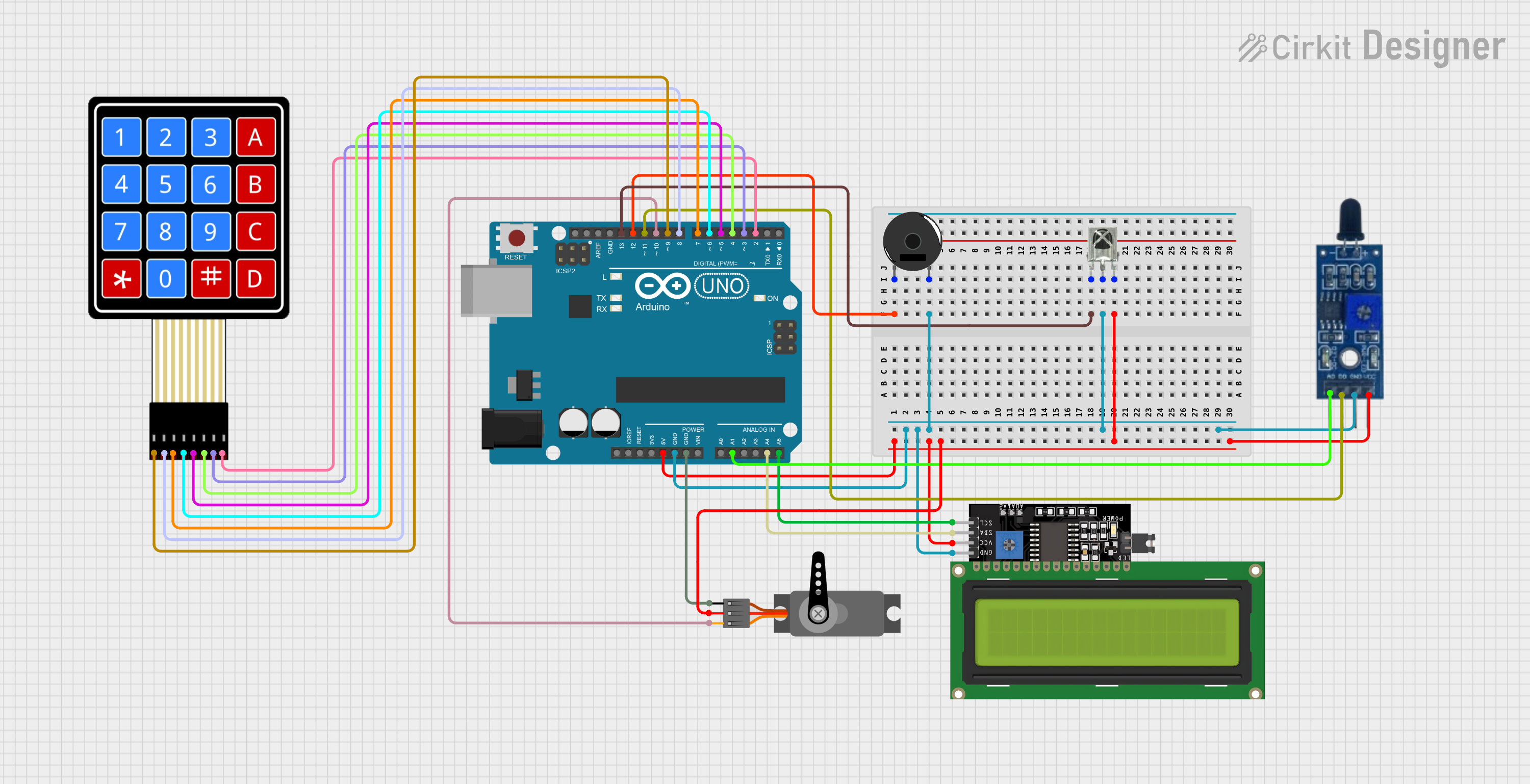
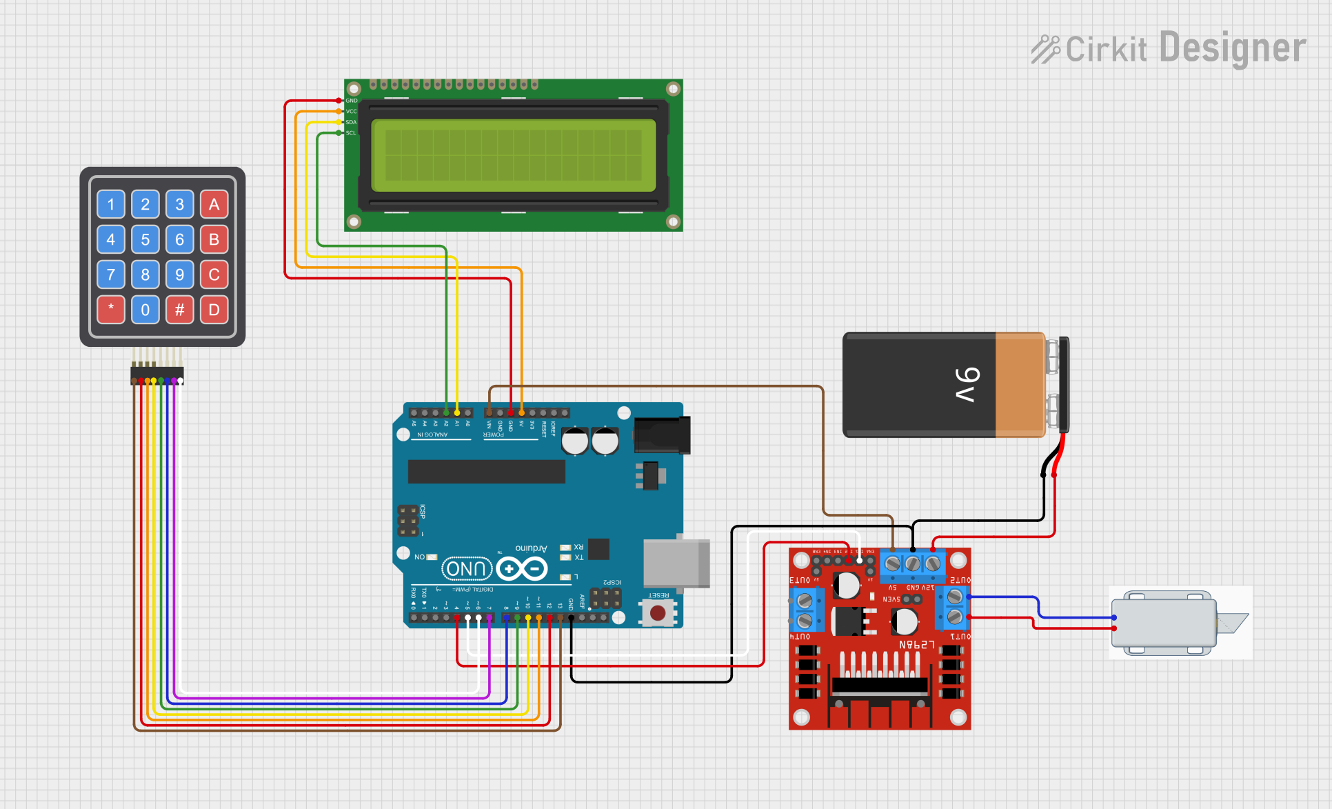
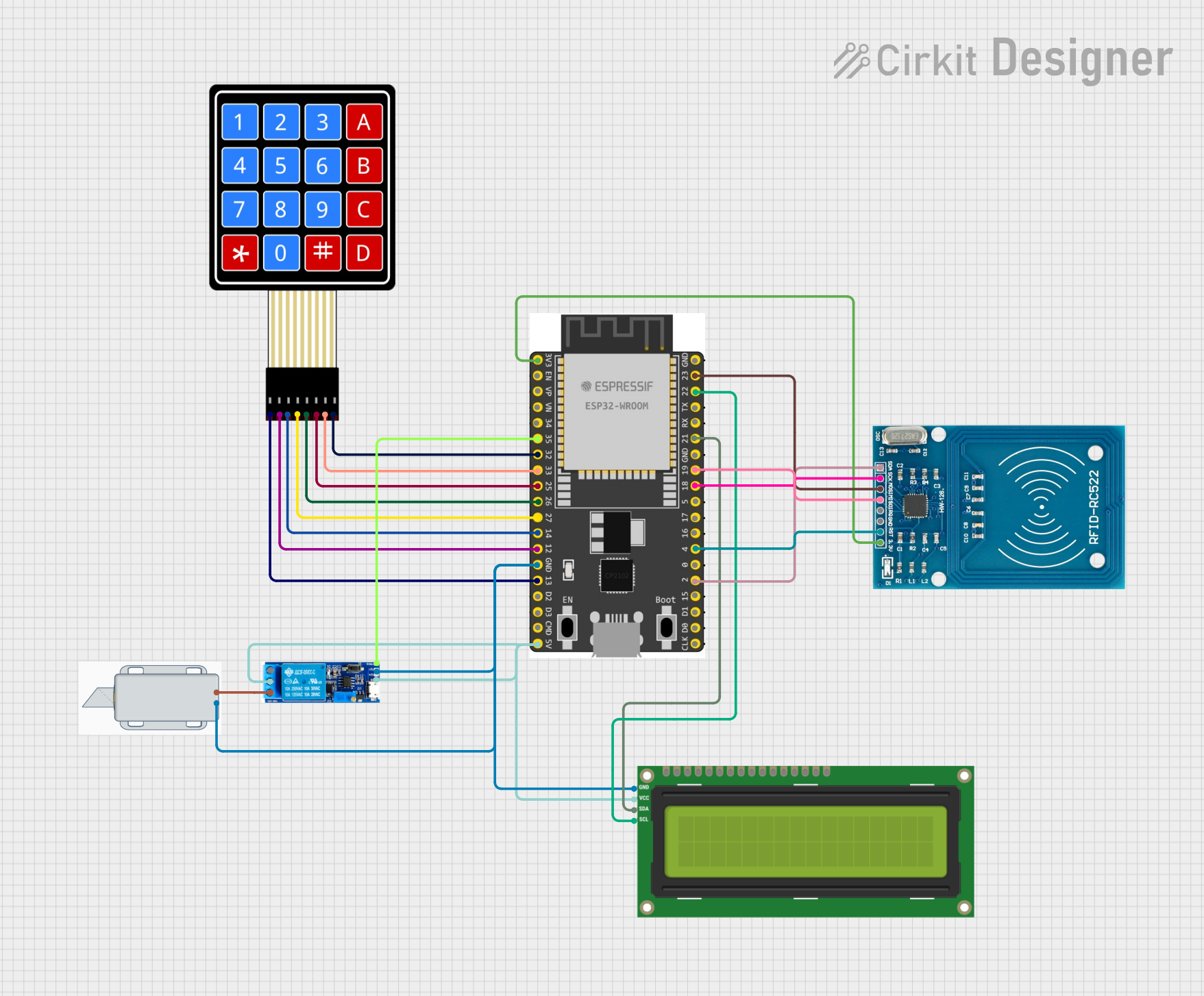
Explore Projects Built with Security Door Lock System
Common Applications and Use Cases
- Residential homes for enhanced safety and convenience.
- Office buildings to control employee access.
- Warehouses and industrial facilities for restricted area management.
- Hotels and rental properties for temporary access control.
- Smart home systems integrated with IoT devices.
Technical Specifications
The following table outlines the key technical details of the SYD Security Door Lock System:
| Parameter | Specification |
|---|---|
| Operating Voltage | 12V DC |
| Current Consumption | 500mA (standby), 1A (active) |
| Lock Type | Electromagnetic or Motorized Deadbolt |
| Access Methods | Keypad, RFID, Biometric (optional) |
| Communication Interface | UART, I2C, or GPIO |
| Operating Temperature | -20°C to 60°C |
| Dimensions | 150mm x 80mm x 30mm |
| Weight | 1.2 kg |
| Material | Stainless Steel and ABS Plastic |
| Security Features | Anti-tamper alarm, auto-lock timeout |
Pin Configuration and Descriptions
The SYD Security Door Lock System has a connector with the following pin configuration:
| Pin Number | Pin Name | Description |
|---|---|---|
| 1 | VCC | Power input (12V DC) |
| 2 | GND | Ground connection |
| 3 | TX | UART Transmit (for communication with controllers) |
| 4 | RX | UART Receive (for communication with controllers) |
| 5 | GPIO1 | General-purpose input/output (e.g., door sensor) |
| 6 | GPIO2 | General-purpose input/output (e.g., alarm output) |
| 7 | RFID_DATA | Data line for RFID reader |
| 8 | BIOMETRIC_DATA | Data line for biometric scanner (optional) |
Usage Instructions
How to Use the Component in a Circuit
- Power Supply: Connect the VCC pin to a 12V DC power source and the GND pin to ground.
- Controller Interface: Use the TX and RX pins to communicate with a microcontroller (e.g., Arduino UNO) for access control logic.
- Access Modules: Attach optional modules like RFID readers or biometric scanners to the respective data pins.
- Door Lock Actuation: Use GPIO pins to monitor door sensors or trigger alarms when tampering is detected.
- Mounting: Secure the lock system to the door frame using the provided screws and brackets.
Important Considerations and Best Practices
- Power Supply: Ensure a stable 12V DC power source to avoid malfunction.
- Wiring: Use shielded cables for communication lines to minimize interference.
- Access Codes: Regularly update keypad codes or RFID credentials for enhanced security.
- Environmental Conditions: Avoid exposing the system to extreme temperatures or moisture.
- Backup Power: Consider using a backup battery to maintain functionality during power outages.
Example: Connecting to an Arduino UNO
Below is an example of how to interface the SYD Security Door Lock System with an Arduino UNO using the UART interface:
#include <SoftwareSerial.h>

// Define RX and TX pins for communication with the lock system
SoftwareSerial lockSystem(10, 11); // RX = pin 10, TX = pin 11

void setup() {
  Serial.begin(9600); // Initialize serial monitor
  lockSystem.begin(9600); // Initialize communication with the lock system

  pinMode(13, OUTPUT); // Optional: Use pin 13 for a status LED
  digitalWrite(13, LOW); // Turn off the LED initially

  Serial.println("Security Door Lock System Initialized");
}

void loop() {
  // Example: Send an unlock command to the lock system
  if (Serial.available()) {
    char command = Serial.read(); // Read command from serial monitor
    if (command == 'U') { // 'U' for unlock
      lockSystem.println("UNLOCK"); // Send unlock command
      digitalWrite(13, HIGH); // Turn on status LED
      delay(5000); // Keep the lock open for 5 seconds
      lockSystem.println("LOCK"); // Send lock command
      digitalWrite(13, LOW); // Turn off status LED
    }
  }

  // Example: Read data from the lock system
  if (lockSystem.available()) {
    String response = lockSystem.readString(); // Read response from lock system
    Serial.println("Lock System Response: " + response);
  }
}
Troubleshooting and FAQs
Common Issues and Solutions
The lock system does not power on.
- Ensure the power supply is 12V DC and properly connected to the VCC and GND pins.
- Check for loose or damaged wires.
The lock does not respond to commands.
- Verify the UART connections (TX and RX) between the lock system and the microcontroller.
- Ensure the baud rate matches the lock system's communication settings (default: 9600).
RFID or biometric scanner is not working.
- Confirm that the module is properly connected to the respective data pins.
- Check the module's compatibility with the lock system.
The lock system triggers false alarms.
- Inspect the GPIO connections for noise or interference.
- Use pull-up or pull-down resistors if necessary.
FAQs
Q: Can the lock system be integrated with a smart home system?
A: Yes, the SYD Security Door Lock System can be integrated with smart home systems using its UART or GPIO interfaces.
Q: What happens during a power outage?
A: The lock system can be paired with a backup battery to maintain functionality during power outages.
Q: Is the system weatherproof?
A: The lock system is designed for indoor use. For outdoor installations, ensure it is housed in a weatherproof enclosure.
Q: Can I reset the system to factory settings?
A: Yes, refer to the manufacturer's manual for the reset procedure, typically involving a specific button sequence.
This concludes the documentation for the SYD Security Door Lock System. For further assistance, refer to the manufacturer's support resources.