Cirkit Designer Logo
Cirkit Designer
Your all-in-one circuit design IDE
Home / 
Component Documentation

How to Use Proto PSA-1 Max7219 Display: Examples, Pinouts, and Specs

Image of Proto PSA-1 Max7219 Display
Cirkit Designer LogoDesign with Proto PSA-1 Max7219 Display in Cirkit Designer

Introduction

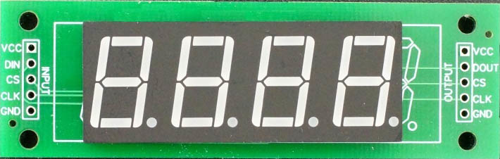
The Proto PSA-1 Max7219 Display is a versatile 8x8 LED matrix module designed for efficient and compact visual output. Manufactured by Proto Supplies, this display module is powered by the MAX7219 LED driver IC, which simplifies the control of multiple LEDs using minimal microcontroller pins. The module is ideal for applications requiring numeric, alphanumeric, or graphical displays.

Common applications include:

  • Digital clocks and counters
  • Scrolling text displays
  • Sensor data visualization
  • Gaming interfaces
  • Educational and hobbyist projects

Explore Projects Built with Proto PSA-1 Max7219 Display

Use Cirkit Designer to design, explore, and prototype these projects online. Some projects support real-time simulation. Click "Open Project" to start designing instantly!
Teensy 4.0 and MAX7219-Based 7-Segment Display Counter
Image of dispay: A project utilizing Proto PSA-1 Max7219 Display in a practical application
This circuit uses a Teensy 4.0 microcontroller to control a MAX7219 LED driver, which in turn drives three 7-segment displays. The microcontroller runs code to display numbers from 0 to 999 on the 7-segment displays, with the SN74AHCT125N buffer providing signal integrity and the necessary capacitors and resistors ensuring stable operation.
Cirkit Designer LogoOpen Project in Cirkit Designer
ESP32-Based Smart Weather Station with LED Display and Multiple Sensors
Image of Copy of Zegarek (1): A project utilizing Proto PSA-1 Max7219 Display in a practical application
This circuit is a sensor and display system powered by an ESP32 microcontroller. It integrates multiple sensors (BH1750 light sensor, BMP280 pressure sensor, DS3231 RTC, and DS18B20 temperature sensor) and drives a series of MAX7219 8x8 LED matrices for visual output. The ESP32 communicates with the sensors via I2C and controls the LED matrices to display data.
Cirkit Designer LogoOpen Project in Cirkit Designer
ESP32-Controlled Multi-Display Interactive System with Pushbutton Inputs
Image of ORBS: A project utilizing Proto PSA-1 Max7219 Display in a practical application
This circuit consists of multiple GC9A01 display modules interfaced with an ESP32 microcontroller. The ESP32 controls the reset (RST), chip select (CS), data/command (DC), serial data (SDA), and serial clock (SCL) lines of each display, allowing for individual communication with each screen. Additionally, there are pushbuttons connected to the ESP32, which could be used for user input to control the displays or other functions within the circuit.
Cirkit Designer LogoOpen Project in Cirkit Designer
ESP32-Based Health Monitoring System with TFT Display and RTC
Image of RemindeRx Circuit Design: A project utilizing Proto PSA-1 Max7219 Display in a practical application
This circuit features an ESP32 microcontroller interfaced with an ILI9341 TFT display, a DS3231 RTC module, and a MAX30102 sensor for health monitoring. The ESP32 handles display updates and sensor data acquisition, while the ULN2003 driver controls a 28BYJ-48 stepper motor. The setup is designed for a health monitoring system with a graphical user interface.
Cirkit Designer LogoOpen Project in Cirkit Designer

Explore Projects Built with Proto PSA-1 Max7219 Display

Use Cirkit Designer to design, explore, and prototype these projects online. Some projects support real-time simulation. Click "Open Project" to start designing instantly!
Image of dispay: A project utilizing Proto PSA-1 Max7219 Display in a practical application
Teensy 4.0 and MAX7219-Based 7-Segment Display Counter
This circuit uses a Teensy 4.0 microcontroller to control a MAX7219 LED driver, which in turn drives three 7-segment displays. The microcontroller runs code to display numbers from 0 to 999 on the 7-segment displays, with the SN74AHCT125N buffer providing signal integrity and the necessary capacitors and resistors ensuring stable operation.
Cirkit Designer LogoOpen Project in Cirkit Designer
Image of Copy of Zegarek (1): A project utilizing Proto PSA-1 Max7219 Display in a practical application
ESP32-Based Smart Weather Station with LED Display and Multiple Sensors
This circuit is a sensor and display system powered by an ESP32 microcontroller. It integrates multiple sensors (BH1750 light sensor, BMP280 pressure sensor, DS3231 RTC, and DS18B20 temperature sensor) and drives a series of MAX7219 8x8 LED matrices for visual output. The ESP32 communicates with the sensors via I2C and controls the LED matrices to display data.
Cirkit Designer LogoOpen Project in Cirkit Designer
Image of ORBS: A project utilizing Proto PSA-1 Max7219 Display in a practical application
ESP32-Controlled Multi-Display Interactive System with Pushbutton Inputs
This circuit consists of multiple GC9A01 display modules interfaced with an ESP32 microcontroller. The ESP32 controls the reset (RST), chip select (CS), data/command (DC), serial data (SDA), and serial clock (SCL) lines of each display, allowing for individual communication with each screen. Additionally, there are pushbuttons connected to the ESP32, which could be used for user input to control the displays or other functions within the circuit.
Cirkit Designer LogoOpen Project in Cirkit Designer
Image of RemindeRx Circuit Design: A project utilizing Proto PSA-1 Max7219 Display in a practical application
ESP32-Based Health Monitoring System with TFT Display and RTC
This circuit features an ESP32 microcontroller interfaced with an ILI9341 TFT display, a DS3231 RTC module, and a MAX30102 sensor for health monitoring. The ESP32 handles display updates and sensor data acquisition, while the ULN2003 driver controls a 28BYJ-48 stepper motor. The setup is designed for a health monitoring system with a graphical user interface.
Cirkit Designer LogoOpen Project in Cirkit Designer

Technical Specifications

The Proto PSA-1 Max7219 Display is built for ease of use and high performance. Below are its key technical details:

General Specifications

Parameter Value
Operating Voltage 5V DC
Operating Current ~40mA (typical)
LED Matrix Dimensions 8x8 (64 LEDs)
Driver IC MAX7219
Communication Protocol SPI (Serial Peripheral Interface)
Module Dimensions 32mm x 32mm

Pin Configuration and Descriptions

The module features a 5-pin header for interfacing with a microcontroller. The pinout is as follows:

Pin Name Description
VCC Power supply input (5V DC)
GND Ground connection
DIN Serial data input (connect to microcontroller MOSI)
CS Chip select (active low, used to enable the module)
CLK Clock input (connect to microcontroller SCK)

Usage Instructions

How to Use the Proto PSA-1 Max7219 Display in a Circuit

  1. Power the Module: Connect the VCC pin to a 5V power source and the GND pin to ground.
  2. Connect to a Microcontroller: Use the SPI interface to connect the DIN, CS, and CLK pins to the corresponding pins on your microcontroller.
  3. Install Required Libraries: If using an Arduino, install the LedControl library, which simplifies communication with the MAX7219 IC.
  4. Write and Upload Code: Use the provided example code or write your own to control the display.

Important Considerations and Best Practices

  • Power Supply: Ensure a stable 5V power source to avoid flickering or damage to the LEDs.
  • Current Limiting: The MAX7219 IC includes built-in current limiting, so no external resistors are required for the LEDs.
  • Daisy-Chaining: Multiple modules can be connected in series for larger displays. Connect the DOUT pin of one module to the DIN pin of the next.
  • Orientation: Ensure the module is oriented correctly when mounting or connecting to avoid reversed text or graphics.

Example Code for Arduino UNO

Below is an example of how to use the Proto PSA-1 Max7219 Display with an Arduino UNO:

#include <LedControl.h> // Include the LedControl library

// Initialize the LedControl object
// Parameters: DIN pin, CLK pin, CS pin, number of displays
LedControl lc = LedControl(12, 11, 10, 1);

void setup() {
  // Wake up the MAX7219 and clear the display
  lc.shutdown(0, false); // Turn off power-saving mode
  lc.setIntensity(0, 8); // Set brightness level (0-15)
  lc.clearDisplay(0);    // Clear the display
}

void loop() {
  // Display a simple pattern on the 8x8 matrix
  for (int row = 0; row < 8; row++) {
    lc.setRow(0, row, 0b10101010); // Set alternating LEDs in each row
    delay(200); // Wait for 200ms
  }
}

Notes on the Code

  • The LedControl library simplifies communication with the MAX7219 IC.
  • Adjust the brightness using setIntensity(). The value ranges from 0 (dim) to 15 (bright).
  • The setRow() function allows you to control individual rows of the LED matrix.

Troubleshooting and FAQs

Common Issues and Solutions

  1. No Display Output:

    • Verify all connections, especially the SPI pins (DIN, CS, CLK).
    • Ensure the module is powered with a stable 5V supply.
    • Check that the LedControl library is installed and included in your code.
  2. Flickering LEDs:

    • Ensure the power supply can provide sufficient current (~40mA per module).
    • Avoid long or thin wires for power connections to reduce voltage drops.
  3. Incorrect or Reversed Display:

    • Verify the orientation of the module. The pin header should match the expected layout.
    • Check the wiring of the SPI pins to ensure they are connected to the correct microcontroller pins.
  4. Unable to Daisy-Chain Modules:

    • Ensure the DOUT pin of one module is connected to the DIN pin of the next.
    • Update the LedControl object initialization to reflect the total number of modules.

FAQs

Q: Can I use a 3.3V microcontroller with this module?
A: The MAX7219 IC requires a 5V power supply, but its logic pins are 3.3V-tolerant. Use level shifters if you encounter communication issues.

Q: How many modules can I daisy-chain?
A: Theoretically, up to 8 modules can be daisy-chained. However, performance may degrade with more modules due to signal attenuation.

Q: Can I display custom graphics?
A: Yes, you can use the setRow() or setColumn() functions to create custom patterns or animations.

By following this documentation, you can effectively integrate the Proto PSA-1 Max7219 Display into your projects for a wide range of applications.