
How to Use Relay LY2N 12VDC: Examples, Pinouts, and Specs
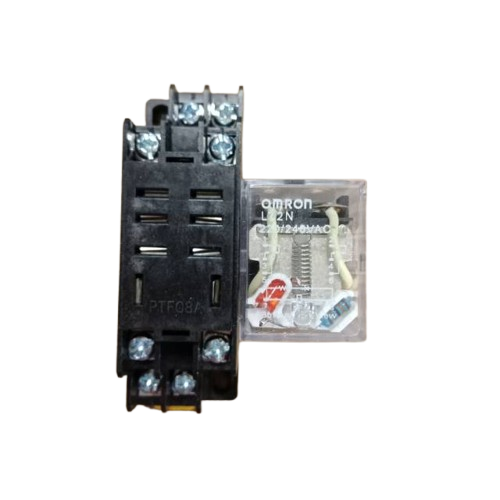
 Design with Relay LY2N 12VDC in Cirkit Designer
Introduction
The Relay LY2N 12VDC, manufactured by Omron, is an electromechanical relay designed for switching applications. It allows low-power control signals (12V DC) to operate high-power loads, making it ideal for automation, industrial control, and home electronics projects. Its compact design and robust performance make it a versatile component for a wide range of applications.
Explore Projects Built with Relay LY2N 12VDC
 Open Project in Cirkit Designer
 Open Project in Cirkit Designer
 Open Project in Cirkit Designer
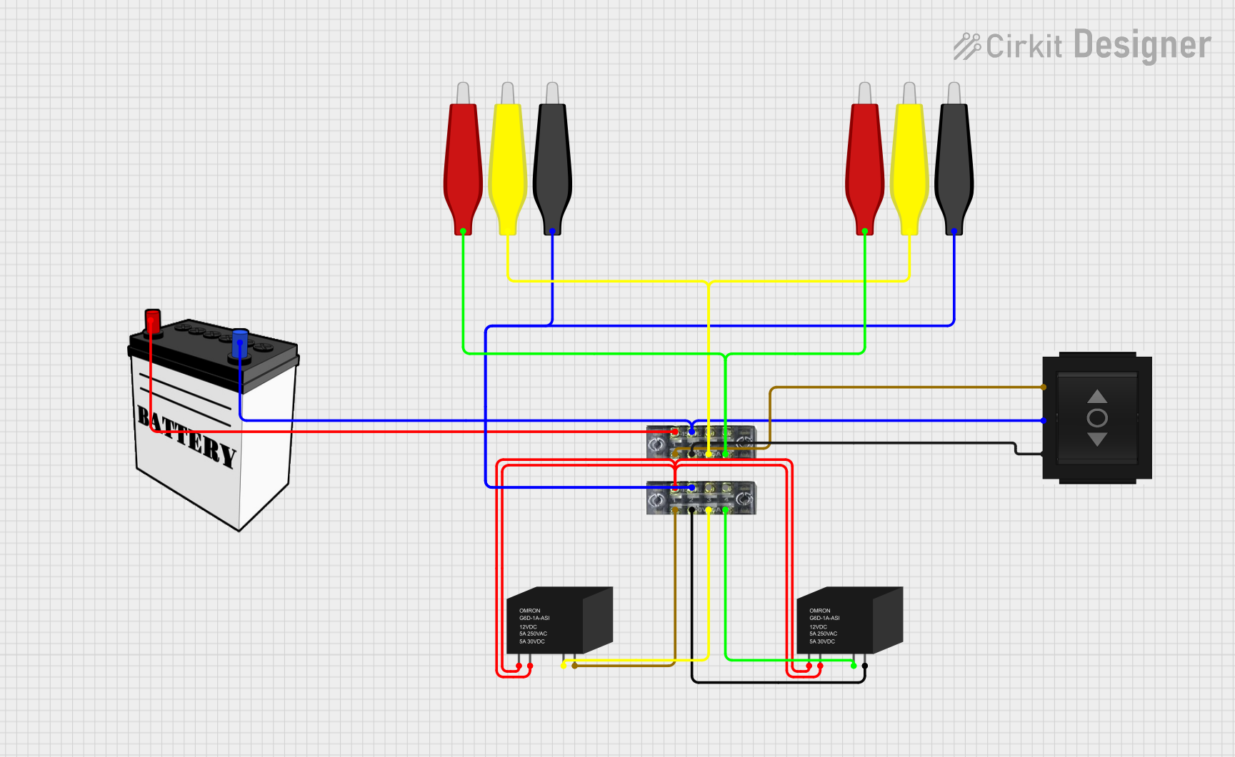 Open Project in Cirkit Designer
Explore Projects Built with Relay LY2N 12VDC
Open Project in Cirkit DesignerOpen Project in Cirkit DesignerOpen Project in Cirkit DesignerOpen Project in Cirkit DesignerCommon Applications
- Industrial automation systems
- Home appliances and HVAC systems
- Motor control circuits
- Lighting control
- Arduino and microcontroller-based projects
Technical Specifications
Below are the key technical details of the Relay LY2N 12VDC:
| Parameter | Value |
|---|---|
| Manufacturer | Omron |
| Part ID | Relay |
| Coil Voltage | 12V DC |
| Coil Resistance | 160 Ω |
| Contact Configuration | DPDT (Double Pole Double Throw) |
| Contact Rating | 10A at 250V AC / 10A at 30V DC |
| Dielectric Strength | 2000V AC (coil to contact) |
| Operating Temperature | -40°C to 70°C |
| Dimensions | 28mm x 21.5mm x 35.5mm |
| Mounting Type | Plug-in or PCB mount |
Pin Configuration and Descriptions
The Relay LY2N 12VDC has a total of 8 pins. The pin configuration is as follows:
| Pin Number | Description |
|---|---|
| 1 | Coil Terminal 1 (Positive) |
| 2 | Coil Terminal 2 (Negative) |
| 3 | Common Terminal for Pole 1 (COM1) |
| 4 | Normally Open Contact for Pole 1 (NO1) |
| 5 | Normally Closed Contact for Pole 1 (NC1) |
| 6 | Common Terminal for Pole 2 (COM2) |
| 7 | Normally Open Contact for Pole 2 (NO2) |
| 8 | Normally Closed Contact for Pole 2 (NC2) |
Usage Instructions
How to Use the Relay LY2N 12VDC in a Circuit
- Power the Coil: Connect the coil terminals (pins 1 and 2) to a 12V DC power source. Ensure the polarity is correct.
- Control the Load: Use the common (COM), normally open (NO), and normally closed (NC) terminals to control the load:
- When the relay is inactive, the COM terminal is connected to the NC terminal.
- When the relay is activated (coil energized), the COM terminal switches to the NO terminal.
- Protect the Circuit: Add a flyback diode across the coil terminals to prevent voltage spikes when the relay is de-energized.
- Mounting: Secure the relay on a PCB or use a compatible socket for plug-in mounting.
Important Considerations and Best Practices
- Current Rating: Ensure the load current does not exceed the relay's contact rating (10A).
- Voltage Isolation: The relay provides electrical isolation between the control circuit and the load circuit, making it safe for high-voltage applications.
- Flyback Diode: Always use a flyback diode (e.g., 1N4007) across the coil terminals to protect the driving circuit from voltage spikes.
- Driving the Relay with Arduino: Use a transistor (e.g., 2N2222) to drive the relay, as the Arduino's GPIO pins cannot supply sufficient current to energize the coil directly.
Example: Connecting the Relay to an Arduino UNO
Below is an example of how to control the Relay LY2N 12VDC using an Arduino UNO:
// Define the pin connected to the transistor base (relay control pin)
const int relayPin = 7;

void setup() {
  pinMode(relayPin, OUTPUT); // Set the relay pin as an output
  digitalWrite(relayPin, LOW); // Ensure the relay is off initially
}

void loop() {
  digitalWrite(relayPin, HIGH); // Turn the relay on
  delay(1000); // Keep the relay on for 1 second
  digitalWrite(relayPin, LOW); // Turn the relay off
  delay(1000); // Keep the relay off for 1 second
}
Circuit Notes:
- Connect the relay's coil terminals to a 12V DC power source.
- Use a transistor (e.g., 2N2222) to switch the relay. The transistor's base is connected to the Arduino pin through a 1kΩ resistor.
- Place a flyback diode (e.g., 1N4007) across the relay coil terminals to protect the transistor and Arduino.
Troubleshooting and FAQs
Common Issues and Solutions
Relay Not Switching:
- Cause: Insufficient voltage or current to the coil.
- Solution: Verify that the coil is receiving 12V DC and sufficient current. Check the power supply and connections.
Voltage Spikes Damaging Components:
- Cause: Absence of a flyback diode across the coil terminals.
- Solution: Install a flyback diode (e.g., 1N4007) across the coil terminals with the cathode connected to the positive terminal.
Contacts Not Conducting Properly:
- Cause: Worn-out or damaged contacts due to excessive current or arcing.
- Solution: Ensure the load current does not exceed the relay's contact rating. Replace the relay if necessary.
Relay Buzzing Noise:
- Cause: Insufficient or unstable voltage to the coil.
- Solution: Check the power supply for stability and ensure it provides a steady 12V DC.
FAQs
Q1: Can I use the Relay LY2N 12VDC with a 5V control signal?
A1: No, the relay requires a 12V DC signal to energize the coil. You can use a transistor or relay driver circuit to interface a 5V control signal with the relay.
Q2: What is the maximum load the relay can handle?
A2: The relay can handle up to 10A at 250V AC or 10A at 30V DC. Ensure the load does not exceed these ratings.
Q3: Can I use this relay for AC loads?
A3: Yes, the relay is suitable for both AC and DC loads, provided the load voltage and current are within the specified ratings.
Q4: How do I know if the relay is working?
A4: When the relay is energized, you should hear a clicking sound as the internal contacts switch. You can also measure continuity between the COM and NO terminals to confirm operation.