
How to Use BTS7960 Motor Driver: Examples, Pinouts, and Specs
 Design with BTS7960 Motor Driver in Cirkit Designer
Introduction
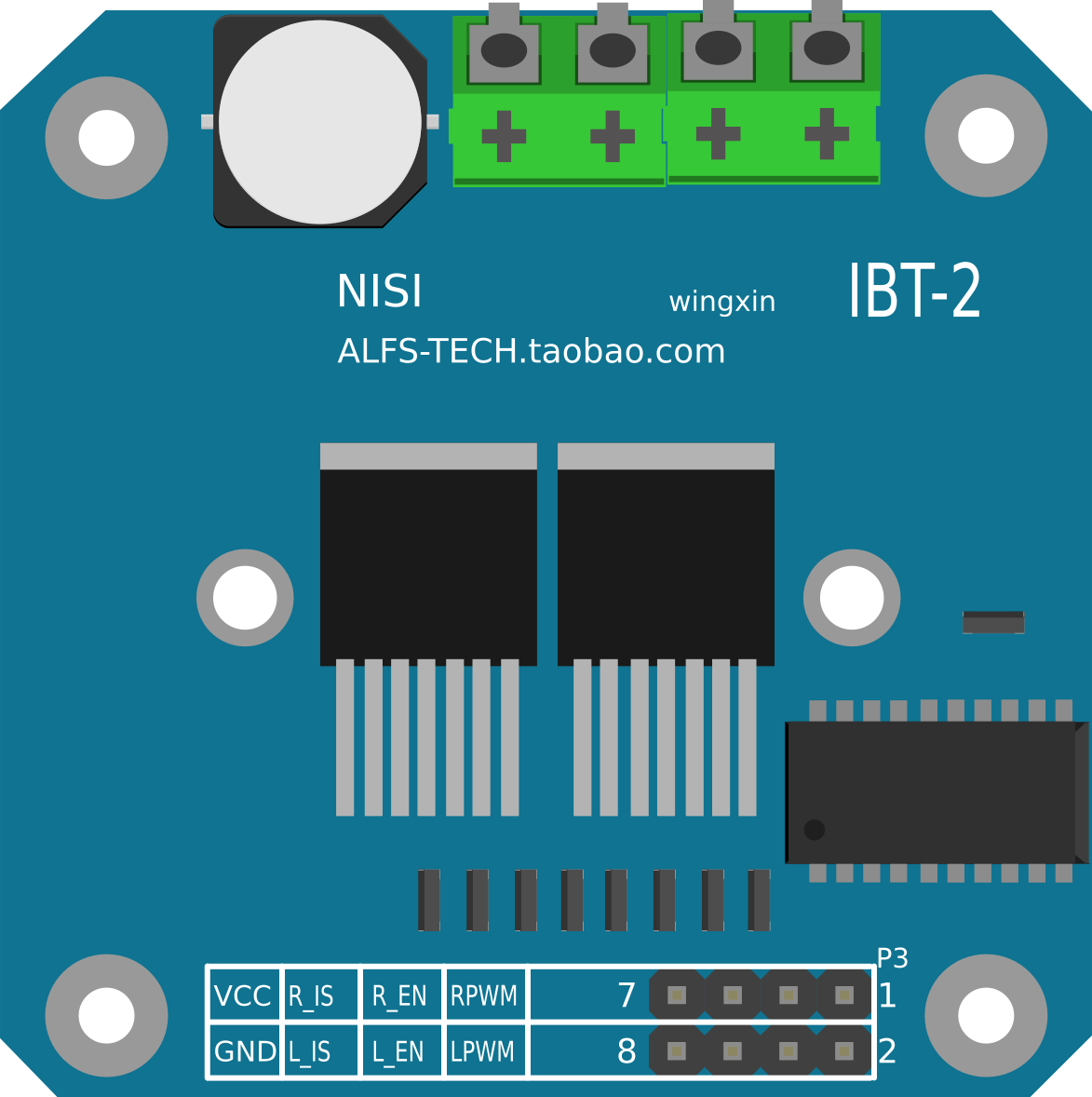
The BTS7960 Motor Driver is a high-power, high-efficiency H-bridge driver module that is capable of driving brushed DC motors. It integrates two H-bridge channels and is capable of providing a continuous current of up to 43A. The BTS7960 is commonly used in robotics, automotive applications, and in any system requiring the control of high-power DC motors.
Explore Projects Built with BTS7960 Motor Driver
 Open Project in Cirkit Designer
 Open Project in Cirkit Designer
 Open Project in Cirkit Designer
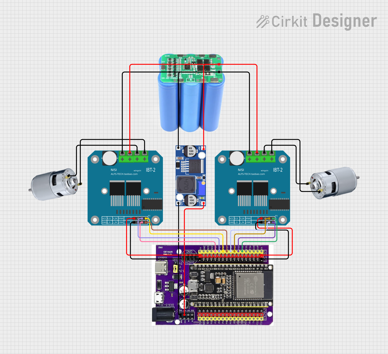
 Open Project in Cirkit Designer
Explore Projects Built with BTS7960 Motor Driver

 Open Project in Cirkit Designer
 Open Project in Cirkit Designer
 Open Project in Cirkit Designer
 Open Project in Cirkit Designer
Common Applications and Use Cases
- Robotics: driving DC motors for wheels, arms, or other moving parts.
- Automotive: controlling electric vehicles' DC motors.
- Industrial automation: driving motors for conveyor belts, pumps, or fans.
- Hobby projects: powering high-current devices in custom builds.
Technical Specifications
Key Technical Details
- Supply Voltage (Vcc): 5.5V to 27V
- Output Current (Continuous): 43A
- Output Peak Current: 45A (short duration)
- PWM Capability: Yes, up to 25kHz
- Logic Level Voltage: 3.3V/5V compatible
- Thermal Shutdown: Yes
- Overcurrent Shutdown: Yes
- Weight: Approximately 30g
Pin Configuration and Descriptions
| Pin Number | Pin Name | Description |
|---|---|---|
| 1 | RPWM | Right PWM input for speed and direction control |
| 2 | LPWM | Left PWM input for speed and direction control |
| 3 | R_EN | Right enable input; active high |
| 4 | L_EN | Left enable input; active high |
| 5 | Vcc | Logic supply voltage (5V typically) |
| 6 | GND | Ground connection |
| 7 | R_IS | Right current sense output |
| 8 | L_IS | Left current sense output |
| 9 | Motor+ | Motor power supply positive |
| 10 | Motor- | Motor power supply negative |
Usage Instructions
How to Use the Component in a Circuit
Power Connections:
- Connect the motor's positive lead to the Motor+ pin (9).
- Connect the motor's negative lead to the Motor- pin (10).
- Connect a suitable power supply to the Motor+ and Motor- pins, ensuring it matches the motor's requirements and does not exceed the BTS7960's voltage rating.
Logic Connections:
- Connect the microcontroller's PWM output pins to the RPWM and LPWM pins for speed and direction control.
- Connect the R_EN and L_EN pins to the microcontroller's digital output pins to enable or disable the motor driver.
- Connect the Vcc pin to the microcontroller's 5V output, and the GND pin to the ground.
Control:
- To drive the motor in one direction, apply a PWM signal to the RPWM pin and set the LPWM pin to LOW.
- To drive the motor in the opposite direction, apply a PWM signal to the LPWM pin and set the RPWM pin to LOW.
- To brake the motor, set both RPWM and LPWM to LOW.
- To let the motor coast, set both RPWM and LPWM to HIGH.
Important Considerations and Best Practices
- Always use a proper heat sink to dissipate heat during operation.
- Ensure that the power supply can handle the motor's current requirements.
- Use flyback diodes across the motor terminals to protect against voltage spikes.
- Avoid running the motor driver at its maximum ratings for extended periods to prevent overheating.
- Implement proper current sensing to prevent damage due to overcurrent conditions.
Troubleshooting and FAQs
Common Issues Users Might Face
- Motor not running: Check power supply connections, ensure that the enable pins are set high, and verify that the PWM signals are being generated correctly.
- Overheating: Make sure a heat sink is attached, reduce the load on the motor, or improve ventilation.
- Erratic motor behavior: Confirm that the logic level voltages are correct and that there is no noise in the PWM signal.
Solutions and Tips for Troubleshooting
- Double-check wiring and solder joints for any loose connections or shorts.
- Use an oscilloscope to verify the PWM signal integrity.
- Ensure that the logic supply voltage (Vcc) is stable and within the specified range.
FAQs
Q: Can I control two motors with one BTS7960? A: Yes, the BTS7960 has two H-bridge channels, allowing you to control two motors independently.
Q: What is the maximum PWM frequency the BTS7960 can handle? A: The BTS7960 can handle PWM frequencies up to 25kHz.
Q: How do I use the current sense output? A: The current sense outputs (R_IS and L_IS) can be connected to an analog input on a microcontroller to monitor the current through the motor.
Example Code for Arduino UNO
// Define the BTS7960 control pins
const int RPWM = 3; // Right PWM pin connected to Arduino pin 3
const int LPWM = 5; // Left PWM pin connected to Arduino pin 5
const int R_EN = 2; // Right Enable pin connected to Arduino pin 2
const int L_EN = 4; // Left Enable pin connected to Arduino pin 4

void setup() {
  // Set the control pins as outputs
  pinMode(RPWM, OUTPUT);
  pinMode(LPWM, OUTPUT);
  pinMode(R_EN, OUTPUT);
  pinMode(L_EN, OUTPUT);

  // Enable the motor driver
  digitalWrite(R_EN, HIGH);
  digitalWrite(L_EN, HIGH);
}

void loop() {
  // Drive motor forward at full speed
  analogWrite(RPWM, 255); // Full speed forward
  digitalWrite(LPWM, LOW); // Ensure LPWM is LOW when driving forward
  delay(2000);             // Run for 2 seconds

  // Brake the motor
  digitalWrite(RPWM, LOW);
  digitalWrite(LPWM, LOW);
  delay(1000);             // Brake for 1 second

  // Drive motor in reverse at half speed
  digitalWrite(RPWM, LOW); // Ensure RPWM is LOW when driving in reverse
  analogWrite(LPWM, 127);  // Half speed reverse
  delay(2000);             // Run for 2 seconds

  // Brake the motor
  digitalWrite(RPWM, LOW);
  digitalWrite(LPWM, LOW);
  delay(1000);             // Brake for 1 second
}
This example demonstrates basic forward and reverse motor control using the BTS7960 motor driver with an Arduino UNO. Adjust the PWM values to control the speed of the motor.