
Cirkit Designer
Your all-in-one circuit design IDE
Home /
Component Documentation
How to Use GND: Examples, Pinouts, and Specs

 Design with GND in Cirkit Designer
Introduction
- GND (Ground) is a fundamental concept and component in electronics. It serves as the reference point in an electrical circuit from which all voltages are measured. Additionally, it acts as the common return path for electric current, ensuring proper circuit operation.
- GND is used in virtually all electronic circuits and systems. Common applications include:
- Providing a stable reference voltage for components.
- Completing electrical circuits by serving as the return path for current.
- Ensuring safety by connecting to earth ground in certain systems to prevent electrical hazards.
Explore Projects Built with GND
12V Multi-Component Control Circuit
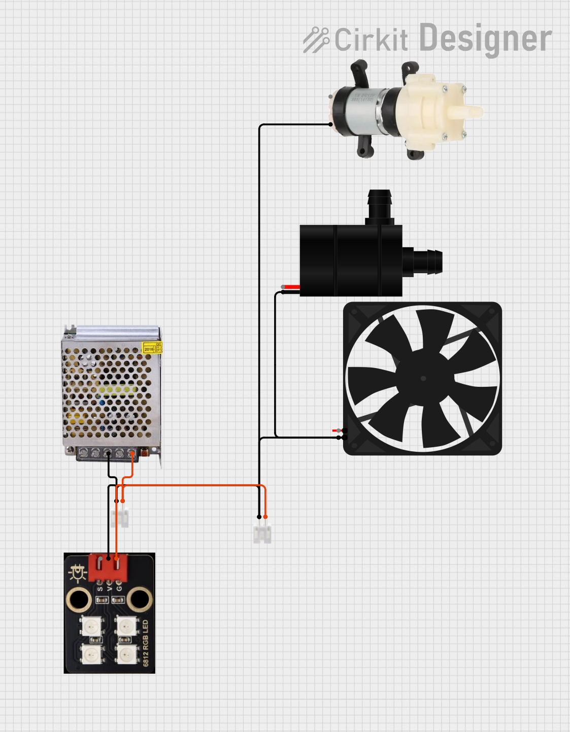
This circuit appears to be a power distribution system that supplies power to various components from a 12V 5A power supply. It connects the negative terminal of the power supply to the ground (GND) pins of a mini diaphragm water pump, an RGB LED, a fan, and a water pump, while the positive DC output is connected to the positive pins of the RGB LED and presumably to other components through JST PH 2.0 connectors. The circuit lacks a controlling element, such as a microcontroller, suggesting that the components operate continuously or are switched externally.
Open Project in Cirkit DesignerPushbutton Interface with General Purpose I/O Plug

This circuit consists of a General Purpose Input/Output (GPIO) plug connected to four pushbuttons. Each pushbutton is wired to a unique input pin on the GPIO plug, allowing the state of each button (pressed or not pressed) to be detected individually. The common terminals of the pushbuttons are interconnected and likely serve as a ground or reference voltage connection.
Open Project in Cirkit DesignerBasic Surge Protection Circuit with Benedict Switch
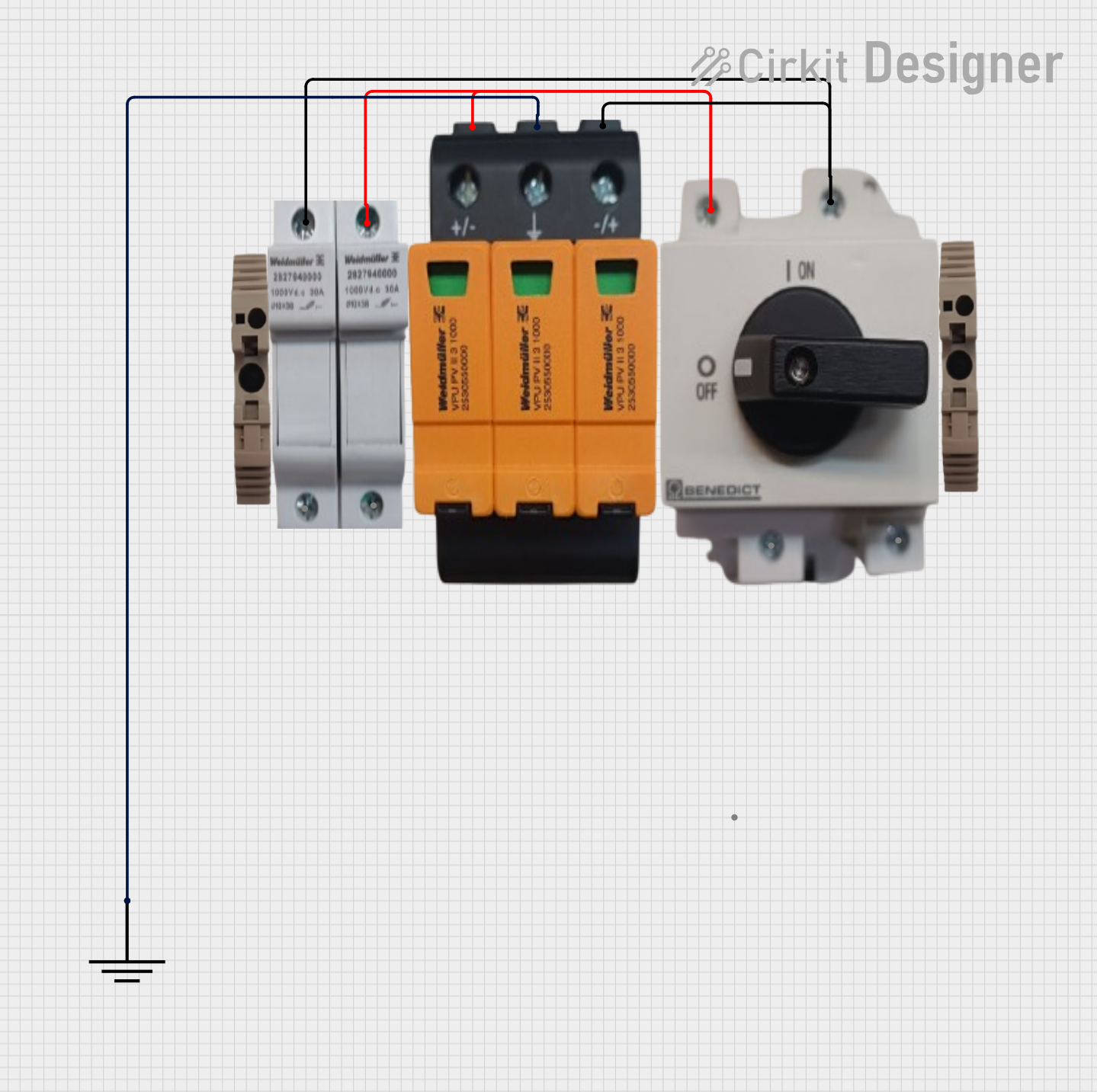
The circuit includes a Benedict Switch connected in series with a Fuse Holder and an SPD (Surge Protection Device). The SPD is also connected to a Ground reference. This configuration suggests that the circuit is designed to control power flow, protect against overcurrent with the fuse, and guard against voltage surges with the SPD, with a safe path to ground for surge dissipation.
Open Project in Cirkit DesignerArduino UNO-Based Sensor Array with Resistor Network
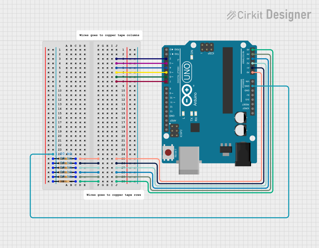
This circuit features an Arduino UNO microcontroller connected to six 1k Ohm resistors. Each resistor is connected between the ground (GND) and one of the analog input pins (A0 to A5) on the Arduino, likely for the purpose of reading analog sensor values or creating a voltage divider network.
Open Project in Cirkit DesignerExplore Projects Built with GND
12V Multi-Component Control Circuit
This circuit appears to be a power distribution system that supplies power to various components from a 12V 5A power supply. It connects the negative terminal of the power supply to the ground (GND) pins of a mini diaphragm water pump, an RGB LED, a fan, and a water pump, while the positive DC output is connected to the positive pins of the RGB LED and presumably to other components through JST PH 2.0 connectors. The circuit lacks a controlling element, such as a microcontroller, suggesting that the components operate continuously or are switched externally.
Open Project in Cirkit DesignerPushbutton Interface with General Purpose I/O Plug
This circuit consists of a General Purpose Input/Output (GPIO) plug connected to four pushbuttons. Each pushbutton is wired to a unique input pin on the GPIO plug, allowing the state of each button (pressed or not pressed) to be detected individually. The common terminals of the pushbuttons are interconnected and likely serve as a ground or reference voltage connection.
Open Project in Cirkit DesignerBasic Surge Protection Circuit with Benedict Switch
The circuit includes a Benedict Switch connected in series with a Fuse Holder and an SPD (Surge Protection Device). The SPD is also connected to a Ground reference. This configuration suggests that the circuit is designed to control power flow, protect against overcurrent with the fuse, and guard against voltage surges with the SPD, with a safe path to ground for surge dissipation.
Open Project in Cirkit DesignerArduino UNO-Based Sensor Array with Resistor Network
This circuit features an Arduino UNO microcontroller connected to six 1k Ohm resistors. Each resistor is connected between the ground (GND) and one of the analog input pins (A0 to A5) on the Arduino, likely for the purpose of reading analog sensor values or creating a voltage divider network.
Open Project in Cirkit DesignerTechnical Specifications
Key Details:
- GND does not have a specific voltage; it is defined as the 0V reference point in a circuit.
- It is typically connected to the negative terminal of a power supply in DC circuits.
- In AC systems, GND may be connected to earth ground for safety.
Pin Configuration and Descriptions: GND is not a physical component with pins but is represented in circuits as a symbol. However, in integrated circuits (ICs) or connectors, GND is often assigned to specific pins. Below is an example of how GND is typically labeled in ICs or connectors:
| Pin Name | Description |
|---|---|
| GND | Ground connection (0V reference). |
Usage Instructions
How to Use GND in a Circuit:
- Identify the GND pin or terminal on your power supply or circuit.
- Connect all components that require a common reference point to the GND node.
- Ensure that the GND connection is consistent throughout the circuit to avoid voltage discrepancies.
Important Considerations and Best Practices:
- Always ensure that GND is properly connected to avoid floating voltages, which can cause erratic behavior in circuits.
- In mixed-signal circuits (e.g., analog and digital), use separate GND planes (e.g., AGND for analog and DGND for digital) and connect them at a single point to minimize noise.
- For safety, in high-power or AC systems, connect GND to earth ground to prevent electrical shocks.
Example: Connecting GND to an Arduino UNO: When using an Arduino UNO, GND is essential for completing the circuit. Below is an example of connecting an LED to the Arduino UNO with GND:
// Example: Blinking an LED with Arduino UNO
// Connect the LED's cathode (short leg) to GND and the anode (long leg) to pin 13.

void setup() {
  pinMode(13, OUTPUT); // Set pin 13 as an output pin
}

void loop() {
  digitalWrite(13, HIGH); // Turn the LED on
  delay(1000);            // Wait for 1 second
  digitalWrite(13, LOW);  // Turn the LED off
  delay(1000);            // Wait for 1 second
}
Troubleshooting and FAQs
Common Issues:
- Floating GND: If GND is not properly connected, components may behave unpredictably.
- Solution: Double-check all GND connections in the circuit.
- Voltage Differences Between GND Points: In large or complex circuits, GND points may have slight voltage differences due to resistance in the connections.
- Solution: Use thicker wires or a dedicated GND plane to minimize resistance.
- Noise in GND: High-frequency noise can appear on the GND line in mixed-signal circuits.
- Solution: Use separate GND planes for analog and digital signals and connect them at a single point.
- Floating GND: If GND is not properly connected, components may behave unpredictably.
FAQs:
- Can I connect multiple components to the same GND?
- Yes, GND is a common reference point, and multiple components can share the same GND connection.
- What happens if GND is not connected?
- Without a proper GND connection, the circuit will not function correctly, as there will be no return path for current.
- Is GND always 0V?
- GND is defined as the 0V reference point in a circuit. However, in some systems, it may not be physically at 0V relative to earth ground due to design considerations.
- Can I connect multiple components to the same GND?