
How to Use ams5935: Examples, Pinouts, and Specs
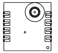
 Design with ams5935 in Cirkit Designer
Introduction
The AMS5935 is a precision voltage reference manufactured by Analog Microelectronics. It provides a stable output voltage with a low temperature coefficient and low noise, making it ideal for high-accuracy applications. This component is commonly used in data acquisition systems, instrumentation, and other precision electronic circuits where a reliable voltage reference is critical.
Explore Projects Built with ams5935
 Open Project in Cirkit Designer
 Open Project in Cirkit Designer
 Open Project in Cirkit Designer
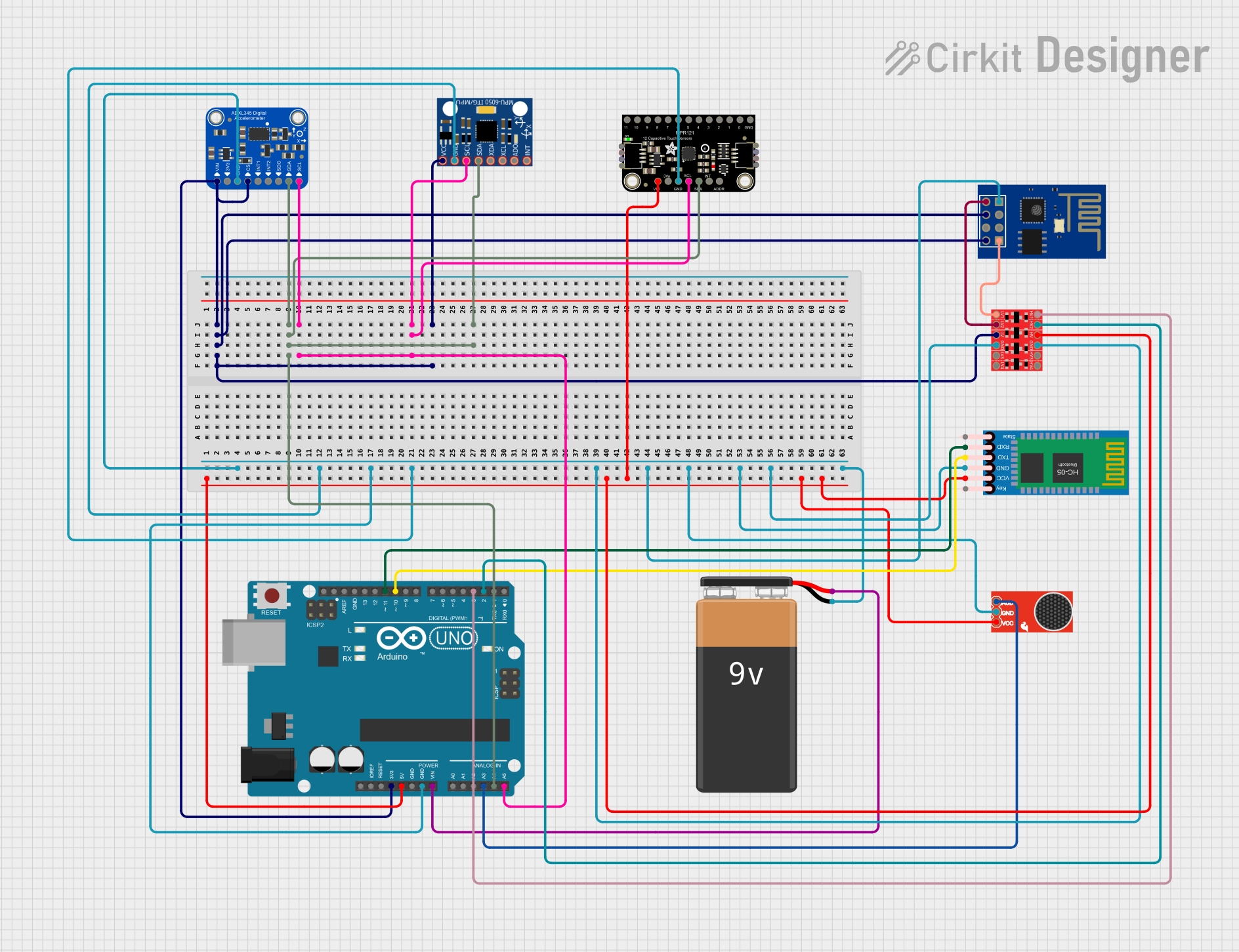
 Open Project in Cirkit Designer
Explore Projects Built with ams5935

 Open Project in Cirkit Designer
 Open Project in Cirkit Designer
 Open Project in Cirkit Designer
 Open Project in Cirkit Designer
Common Applications:
- Data acquisition systems
- Instrumentation and measurement equipment
- Analog-to-digital converters (ADCs)
- Digital-to-analog converters (DACs)
- Precision power supplies
Technical Specifications
The AMS5935 is designed to deliver high performance in demanding applications. Below are its key technical specifications:
| Parameter | Value |
|---|---|
| Output Voltage | 2.5V, 3.0V, 3.3V, 5.0V (varies by model) |
| Output Voltage Tolerance | ±0.2% |
| Temperature Coefficient | 10 ppm/°C (typical) |
| Supply Voltage Range | 4.5V to 12V |
| Supply Current | 1.0 mA (typical) |
| Output Noise (0.1Hz–10Hz) | 10 µV RMS (typical) |
| Operating Temperature Range | -40°C to +125°C |
| Package Options | SOT-23, SOIC-8 |
Pin Configuration
The AMS5935 is available in multiple package types. Below is the pin configuration for the SOT-23 package:
| Pin Number | Pin Name | Description |
|---|---|---|
| 1 | VIN | Input voltage |
| 2 | GND | Ground |
| 3 | VOUT | Output voltage |
For the SOIC-8 package, the pin configuration is as follows:
| Pin Number | Pin Name | Description |
|---|---|---|
| 1 | NC | No connection |
| 2 | VIN | Input voltage |
| 3 | GND | Ground |
| 4 | NC | No connection |
| 5 | NC | No connection |
| 6 | NC | No connection |
| 7 | GND | Ground |
| 8 | VOUT | Output voltage |
Usage Instructions
The AMS5935 is straightforward to use in a circuit. Follow these steps and considerations to ensure optimal performance:
Basic Circuit Connection
- Power Supply: Connect the VIN pin to a stable DC power supply within the specified range (4.5V to 12V).
- Ground: Connect the GND pin to the circuit ground.
- Output: The VOUT pin provides the precision reference voltage. Connect this pin to the load or circuit requiring the reference voltage.
Important Considerations
- Bypass Capacitor: Place a 0.1 µF ceramic capacitor close to the VIN pin to filter out noise from the power supply.
- Load Capacitance: To ensure stability, connect a capacitor (e.g., 1 µF) between the VOUT pin and GND.
- Thermal Management: Ensure adequate thermal dissipation, especially in high-temperature environments.
- Avoid Overloading: Do not exceed the maximum output current rating to maintain accuracy and prevent damage.
Example: Using AMS5935 with Arduino UNO
The AMS5935 can be used as a reference voltage for ADCs in microcontrollers like the Arduino UNO. Below is an example of how to connect and use it:
Circuit Diagram
- Connect the AMS5935's VOUT pin to the AREF pin of the Arduino UNO.
- Connect the GND pin of the AMS5935 to the Arduino's GND.
- Connect the VIN pin of the AMS5935 to a 5V power supply.
Arduino Code Example
// Example code to use AMS5935 as an external reference voltage for Arduino ADC

void setup() {
  // Set the analog reference to EXTERNAL to use AMS5935
  analogReference(EXTERNAL);

  // Initialize serial communication for debugging
  Serial.begin(9600);
}

void loop() {
  // Read an analog value from pin A0
  int sensorValue = analogRead(A0);

  // Convert the ADC value to voltage using the AMS5935 reference
  // Assuming AMS5935 provides a 2.5V reference
  float voltage = sensorValue * (2.5 / 1023.0);

  // Print the voltage to the serial monitor
  Serial.print("Voltage: ");
  Serial.print(voltage);
  Serial.println(" V");

  delay(1000); // Wait for 1 second before the next reading
}
Notes:
- Ensure the AMS5935 output voltage matches the Arduino's AREF pin requirements.
- Use proper decoupling capacitors to minimize noise.
Troubleshooting and FAQs
Common Issues and Solutions
No Output Voltage:
- Verify that the VIN pin is connected to a stable power supply within the specified range.
- Check for proper grounding of the GND pin.
- Ensure the load connected to the VOUT pin does not exceed the maximum current rating.
Unstable Output Voltage:
- Add a bypass capacitor (0.1 µF) near the VIN pin to filter power supply noise.
- Ensure a load capacitor (e.g., 1 µF) is connected between VOUT and GND.
High Noise on Output:
- Use low-ESR capacitors for bypassing and load capacitance.
- Minimize external noise sources near the AMS5935.
Overheating:
- Check for excessive input voltage or current draw.
- Improve thermal dissipation by using a heatsink or ensuring proper airflow.
FAQs
Q: Can the AMS5935 be used with a 3.3V power supply?
A: No, the minimum input voltage for the AMS5935 is 4.5V. Ensure the power supply is within the 4.5V to 12V range.
Q: What is the maximum output current of the AMS5935?
A: The AMS5935 is designed for low-current applications and can typically source up to 10 mA. Check the datasheet for specific details.
Q: Can I use the AMS5935 in a high-temperature environment?
A: Yes, the AMS5935 operates reliably within a temperature range of -40°C to +125°C. However, ensure proper thermal management to avoid overheating.
Q: Is the AMS5935 suitable for battery-powered applications?
A: Yes, its low supply current (1.0 mA typical) makes it suitable for battery-powered systems, provided the input voltage is within the specified range.
By following the guidelines and recommendations in this documentation, you can effectively integrate the AMS5935 into your precision electronic designs.