How to Use AOD4184: Examples, Pinouts, and Specs
Introduction
The AOD4184 is an N-channel MOSFET designed for high-speed switching applications. It features low on-resistance and fast switching capabilities, making it ideal for use in power management systems, DC-DC converters, motor drivers, and other high-efficiency power circuits. Its robust design and high current-handling capacity make it a popular choice for both industrial and hobbyist applications.
Explore Projects Built with AOD4184

Explore Projects Built with AOD4184
Common Applications
- DC-DC converters
- Motor control circuits
- Power management in embedded systems
- Battery-powered devices
- High-efficiency switching regulators
Technical Specifications
The AOD4184 is optimized for performance in low-voltage, high-current applications. Below are its key technical details:
| Parameter | Value |
|---|---|
| Drain-Source Voltage (VDS) | 40V |
| Gate-Source Voltage (VGS) | ±20V |
| Continuous Drain Current (ID) | 50A (at 25°C) |
| Pulsed Drain Current (IDM) | 200A |
| On-Resistance (RDS(on)) | 6.5mΩ (at VGS = 10V) |
| Total Gate Charge (Qg) | 36nC |
| Power Dissipation (PD) | 50W |
| Operating Temperature Range | -55°C to +175°C |
| Package Type | TO-252 (DPAK) |
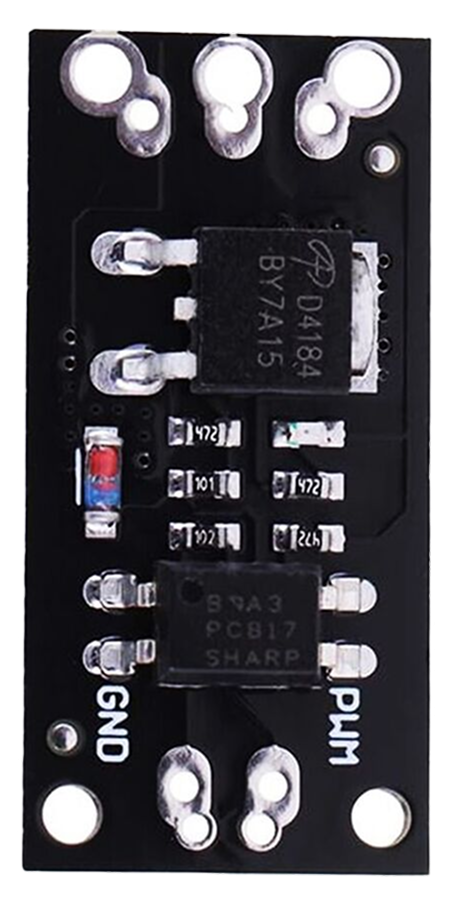
Pin Configuration
The AOD4184 is typically available in a TO-252 (DPAK) package. The pinout is as follows:
| Pin Number | Pin Name | Description |
|---|---|---|
| 1 | Gate | Controls the MOSFET switching state |
| 2 | Drain | Main current-carrying terminal |
| 3 | Source | Connected to ground or load return |
| Tab | Drain | Electrically connected to the drain |
Usage Instructions
The AOD4184 is straightforward to use in a variety of circuits. Below are the steps and considerations for incorporating it into your design:
Basic Circuit Connection
- Gate Control: Connect the gate pin to a control signal (e.g., from a microcontroller or driver circuit). Use a resistor (typically 10Ω to 100Ω) in series with the gate to limit inrush current and prevent oscillations.
- Drain Connection: Connect the drain pin to the positive side of the load.
- Source Connection: Connect the source pin to ground or the negative side of the load.
Important Considerations
- Ensure the gate voltage (VGS) is within the specified range (±20V). For optimal performance, drive the gate with at least 10V.
- Use a proper heatsink or PCB thermal design to dissipate heat, especially when operating at high currents.
- Avoid exceeding the maximum drain-source voltage (40V) to prevent damage to the MOSFET.
- For high-speed switching, minimize the gate capacitance by using a low-impedance gate driver.
Example: Using AOD4184 with Arduino UNO
The AOD4184 can be used to control a DC motor with an Arduino UNO. Below is an example circuit and code:
Circuit Diagram
- Connect the drain of the AOD4184 to one terminal of the motor.
- Connect the source to ground.
- Connect the other terminal of the motor to the positive supply (e.g., 12V).
- Connect the gate to an Arduino digital pin (e.g., D9) through a 100Ω resistor.
- Place a flyback diode (e.g., 1N4007) across the motor terminals to protect against voltage spikes.
Arduino Code
// AOD4184 MOSFET control example
// This code demonstrates how to use the AOD4184 to control a DC motor
// using PWM from an Arduino UNO.

const int motorPin = 9; // Pin connected to the MOSFET gate

void setup() {
  pinMode(motorPin, OUTPUT); // Set the motor pin as an output
}

void loop() {
  analogWrite(motorPin, 128); // Set motor speed to 50% (PWM value: 128)
  delay(5000);               // Run motor for 5 seconds

  analogWrite(motorPin, 0);  // Turn off the motor
  delay(5000);               // Wait for 5 seconds
}
Best Practices
- Use a gate driver IC for high-frequency switching to ensure fast and efficient operation.
- Add a pull-down resistor (10kΩ) between the gate and source to prevent accidental turn-on due to floating gate voltage.
- Use decoupling capacitors near the power supply to reduce noise and voltage spikes.
Troubleshooting and FAQs
Common Issues
MOSFET Overheating
- Cause: Insufficient heatsinking or excessive current.
- Solution: Use a heatsink or improve PCB thermal design. Ensure the current is within the rated limit.
MOSFET Not Switching
- Cause: Insufficient gate voltage or incorrect wiring.
- Solution: Verify the gate voltage is at least 10V for full enhancement. Check the circuit connections.
Motor Not Running
- Cause: Faulty wiring or damaged MOSFET.
- Solution: Check all connections and replace the MOSFET if necessary.
Voltage Spikes Damaging the MOSFET
- Cause: Inductive loads generating back EMF.
- Solution: Add a flyback diode across the load to suppress voltage spikes.
FAQs
Q: Can the AOD4184 be used with 3.3V logic?
A: The AOD4184 requires a gate voltage of at least 10V for optimal performance. Use a level shifter or gate driver if controlling it with 3.3V logic.
Q: What is the maximum switching frequency?
A: The maximum switching frequency depends on the gate driver and load conditions. With a proper gate driver, it can operate in the hundreds of kHz range.
Q: How do I calculate the power dissipation?
A: Power dissipation can be estimated using the formula:
P = I2 × RDS(on)
where I is the drain current and RDS(on) is the on-resistance.
By following this documentation, you can effectively integrate the AOD4184 into your electronic designs and troubleshoot common issues.