How to Use Adafruit 2.4 Inch TFT LCD Breakout Board: Examples, Pinouts, and Specs
Adafruit 2.4 Inch TFT LCD Breakout Board Documentation
1. Introduction
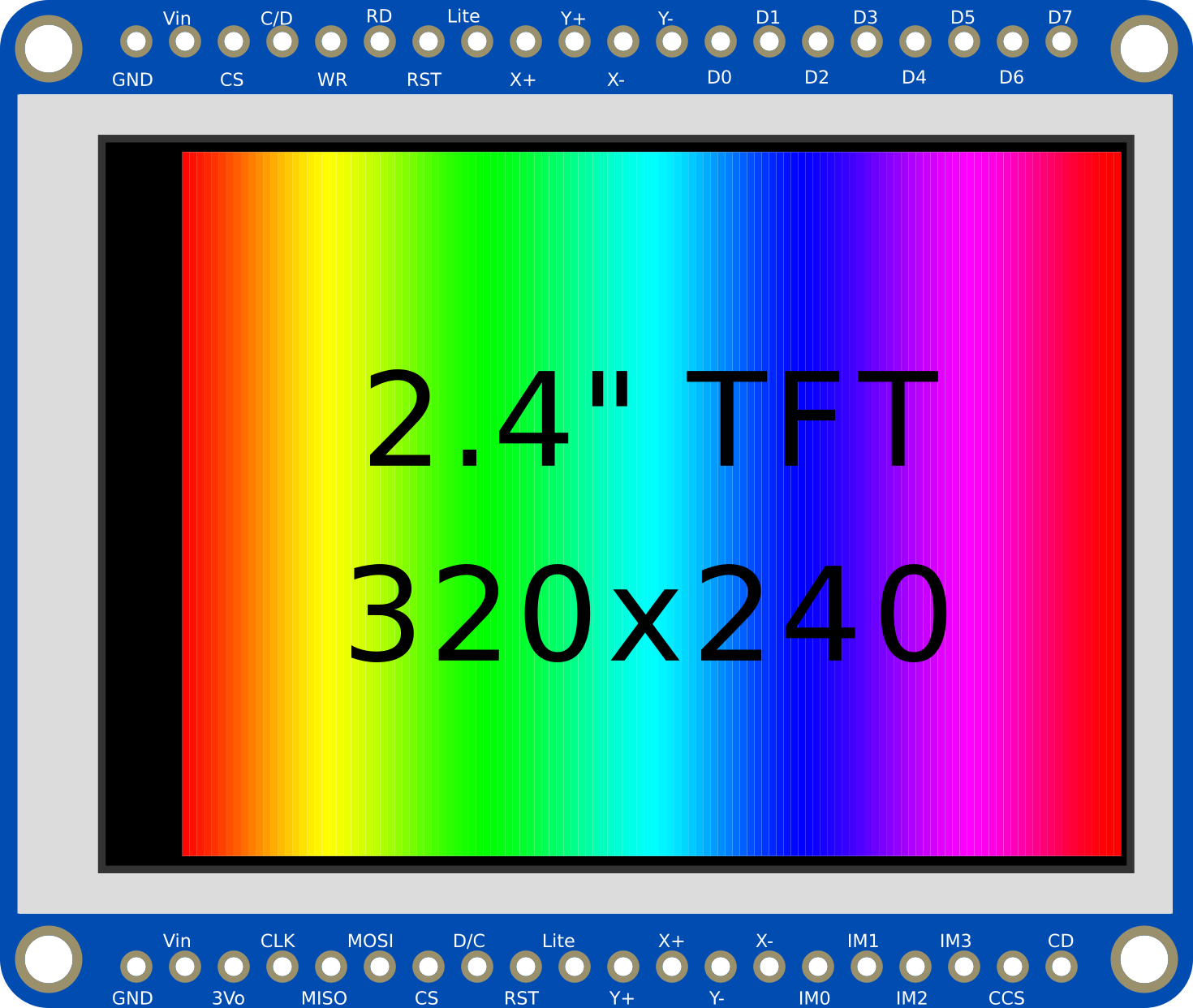
The Adafruit 2.4 Inch TFT LCD Breakout Board is a compact and versatile display module featuring a 2.4-inch TFT LCD screen. It is designed for projects that require high-quality visual output and supports touch input for interactive applications. This module is compatible with a wide range of microcontrollers, including the Arduino UNO, making it an excellent choice for hobbyists, students, and professionals alike.
Key Features:
- 2.4-inch full-color TFT LCD display with a resolution of 240x320 pixels.
- Integrated resistive touch screen for interactive input.
- SPI interface for efficient communication with microcontrollers.
- Compact design, ideal for portable and embedded systems.
- Wide compatibility with Arduino, Raspberry Pi, and other platforms.
Common Applications:
- Graphical user interfaces (GUIs) for embedded systems.
- Data visualization (e.g., graphs, charts, and sensor readings).
- Interactive projects with touch input.
- Portable devices requiring a compact display.
- Educational projects and prototyping.
2. Technical Specifications
The following table outlines the key technical details of the Adafruit 2.4 Inch TFT LCD Breakout Board:
| Parameter | Specification |
|---|---|
| Display Type | TFT LCD |
| Screen Size | 2.4 inches |
| Resolution | 240 x 320 pixels |
| Color Depth | 16-bit (65,536 colors) |
| Touch Screen Type | Resistive |
| Communication Interface | SPI |
| Operating Voltage | 3.3V (logic level) |
| Backlight Voltage | 3.3V |
| Current Consumption | ~50mA (varies with backlight brightness) |
| Dimensions | 42mm x 60mm x 5mm |
Pin Configuration and Descriptions
The breakout board has several pins for power, communication, and control. Below is the pinout:
| Pin Name | Description |
|---|---|
| VIN | Power input (3.3V or 5V). |
| GND | Ground connection. |
| SCK | SPI clock input. |
| MISO | SPI Master-In-Slave-Out (not used in most cases). |
| MOSI | SPI Master-Out-Slave-In. |
| CS | Chip Select (active low). |
| DC | Data/Command control pin. |
| RST | Reset pin (active low). |
| T_CLK | Touch screen SPI clock. |
| T_CS | Touch screen chip select. |
| T_DIN | Touch screen SPI data input. |
| T_DO | Touch screen SPI data output. |
| T_IRQ | Touch screen interrupt pin (active low, optional for touch detection). |
| LED | Backlight control (connect to 3.3V for full brightness or use PWM for dimming). |
3. Usage Instructions
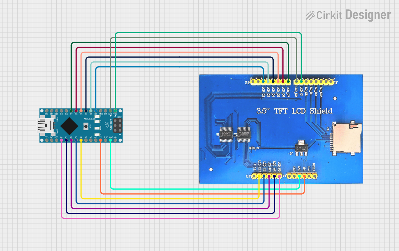
Connecting the Display to an Arduino UNO
To use the Adafruit 2.4 Inch TFT LCD Breakout Board with an Arduino UNO, follow these steps:
Wiring the Display: Connect the breakout board to the Arduino UNO as shown in the table below:
Breakout Pin Arduino UNO Pin VIN 5V GND GND SCK D13 MOSI D11 CS D10 DC D9 RST D8 LED 3.3V (or PWM pin) For touch functionality, connect the following additional pins:
Breakout Pin Arduino UNO Pin T_CLK D13 T_CS D4 T_DIN D11 T_DO D12 T_IRQ D2 (optional) Install Required Libraries:
- Install the Adafruit GFX library and Adafruit ILI9341 library from the Arduino Library Manager.
- For touch functionality, install the Adafruit TouchScreen library.
Upload Example Code: Use the example code below to test the display and touch functionality.
Example Code
#include <Adafruit_GFX.h>       // Core graphics library
#include <Adafruit_ILI9341.h>   // Driver for the ILI9341 display
#include <TouchScreen.h>        // Library for touch functionality

// Pin definitions for the display
#define TFT_CS   10  // Chip select
#define TFT_DC   9   // Data/command
#define TFT_RST  8   // Reset

// Pin definitions for the touch screen
#define TS_CS    4   // Touch screen chip select
#define TS_CLK   13  // Touch screen clock
#define TS_DIN   11  // Touch screen data input
#define TS_DOUT  12  // Touch screen data output
#define TS_IRQ   2   // Touch screen interrupt (optional)

// Initialize display and touch screen objects
Adafruit_ILI9341 tft = Adafruit_ILI9341(TFT_CS, TFT_DC, TFT_RST);
TouchScreen ts = TouchScreen(TS_CLK, TS_DIN, TS_DOUT, TS_CS, 300);

// Calibration values for the touch screen
#define MINPRESSURE 10
#define MAXPRESSURE 1000

void setup() {
  Serial.begin(9600);
  tft.begin();  // Initialize the display
  tft.setRotation(1);  // Set display orientation
  tft.fillScreen(ILI9341_BLACK);  // Clear the screen
  tft.setTextColor(ILI9341_WHITE);
  tft.setTextSize(2);
  tft.setCursor(10, 10);
  tft.println("Hello, TFT!");
}

void loop() {
  // Read touch input
  TSPoint p = ts.getPoint();

  // Check if the screen is being touched
  if (p.z > MINPRESSURE && p.z < MAXPRESSURE) {
    // Map touch coordinates to screen coordinates
    int x = map(p.x, 200, 3800, 0, tft.width());
    int y = map(p.y, 200, 3800, 0, tft.height());

    // Draw a circle at the touch point
    tft.fillCircle(x, y, 3, ILI9341_RED);
  }
}
4. Troubleshooting and FAQs
Common Issues and Solutions
The display does not turn on:
- Ensure the VIN and GND pins are properly connected to the Arduino's 5V and GND pins.
- Verify that the backlight pin (LED) is connected to 3.3V or a PWM pin.
The screen shows random colors or does not display correctly:
- Check the SPI connections (SCK, MOSI, CS, DC, and RST).
- Ensure the correct libraries are installed and initialized in the code.
Touch input is not working:
- Verify the touch screen pins (T_CLK, T_CS, T_DIN, T_DO, and T_IRQ) are correctly connected.
- Check the calibration values in the code and adjust them if necessary.
The display is flickering:
- Use a stable power source and ensure proper grounding.
- If using PWM for the backlight, ensure the frequency is high enough to avoid visible flicker.
FAQs
Q: Can I use this display with a 5V logic microcontroller?
A: Yes, the breakout board includes level-shifting circuitry, making it compatible with 5V logic.
Q: How do I adjust the brightness of the backlight?
A: Connect the LED pin to a PWM-capable pin on your microcontroller and use analogWrite() to control brightness.
Q: Can I use this display with a Raspberry Pi?
A: Yes, the display is compatible with Raspberry Pi. You will need to use the SPI interface and appropriate libraries.
This documentation provides a comprehensive guide to using the Adafruit 2.4 Inch TFT LCD Breakout Board. Whether you're a beginner or an experienced user, this guide will help you integrate the display into your projects effectively.
Explore Projects Built with Adafruit 2.4 Inch TFT LCD Breakout Board


Explore Projects Built with Adafruit 2.4 Inch TFT LCD Breakout Board