
How to Use 4 Channel Mosfet: Examples, Pinouts, and Specs
 Design with 4 Channel Mosfet in Cirkit Designer
Introduction
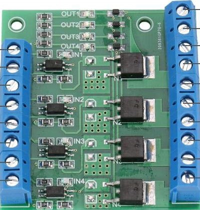
The 4 Channel MOSFET (Manufacturer: Hilitand, Part ID: X002W2O687) is a versatile electronic component designed for switching and amplifying electronic signals. It features four independent MOSFET channels, enabling it to control multiple loads or signals simultaneously. This makes it an excellent choice for applications requiring efficient power management, signal amplification, or load switching.
Explore Projects Built with 4 Channel Mosfet
 Open Project in Cirkit Designer
 Open Project in Cirkit Designer
 Open Project in Cirkit Designer
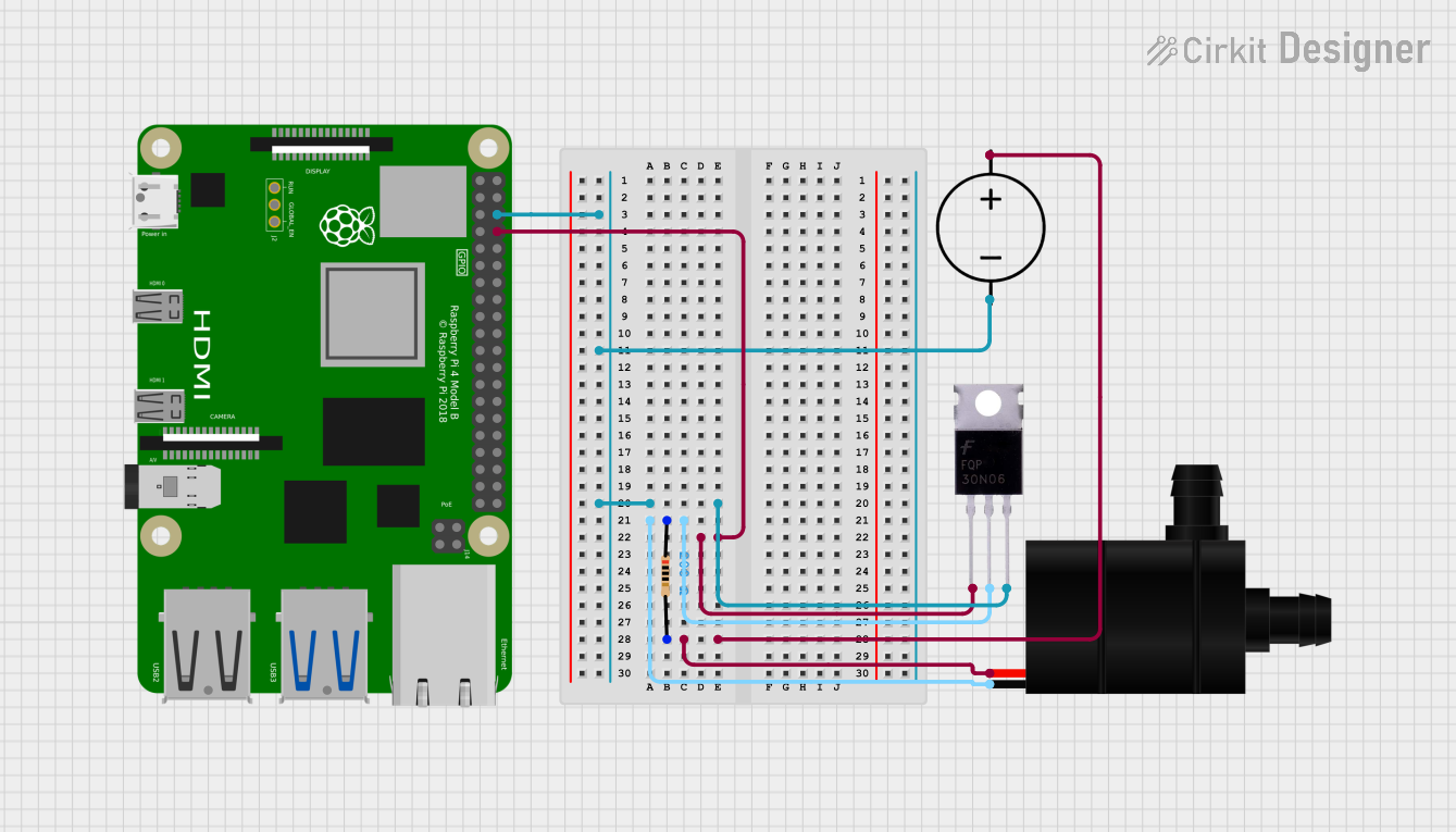 Open Project in Cirkit Designer
Explore Projects Built with 4 Channel Mosfet
Open Project in Cirkit DesignerOpen Project in Cirkit DesignerOpen Project in Cirkit DesignerOpen Project in Cirkit DesignerCommon Applications
- Motor control in robotics and automation
- LED dimming and lighting control
- Power management in battery-operated devices
- Signal amplification in audio and RF circuits
- Switching high-current loads in industrial systems
Technical Specifications
Key Specifications
| Parameter | Value |
|---|---|
| Manufacturer | Hilitand |
| Part ID | X002W2O687 |
| Number of Channels | 4 |
| Operating Voltage | 3.3V to 20V |
| Maximum Drain Current | 10A per channel |
| Maximum Power Dissipation | 25W per channel |
| Gate Threshold Voltage | 2V to 4V |
| On-Resistance (RDS(on)) | < 0.1Ω |
| Operating Temperature | -55°C to +150°C |
| PCB Mounting Type | Through-hole or SMD |
Pin Configuration and Descriptions
The 4 Channel MOSFET module typically has the following pin layout:
| Pin Number | Pin Name | Description |
|---|---|---|
| 1 | VCC | Power supply input (3.3V to 20V) |
| 2 | GND | Ground connection |
| 3 | IN1 | Control signal input for Channel 1 |
| 4 | IN2 | Control signal input for Channel 2 |
| 5 | IN3 | Control signal input for Channel 3 |
| 6 | IN4 | Control signal input for Channel 4 |
| 7 | OUT1 | Output for Channel 1 (connect to load) |
| 8 | OUT2 | Output for Channel 2 (connect to load) |
| 9 | OUT3 | Output for Channel 3 (connect to load) |
| 10 | OUT4 | Output for Channel 4 (connect to load) |
Usage Instructions
How to Use the 4 Channel MOSFET in a Circuit
- Power Supply: Connect the VCC pin to a power source within the operating voltage range (3.3V to 20V). Connect the GND pin to the ground of the circuit.
- Control Signals: Apply control signals (e.g., from a microcontroller like Arduino) to the IN1, IN2, IN3, and IN4 pins. These signals determine whether the corresponding MOSFET channels are ON or OFF.
- Load Connections: Connect the loads (e.g., motors, LEDs) to the OUT1, OUT2, OUT3, and OUT4 pins. Ensure the load current does not exceed the maximum drain current (10A per channel).
- Gate Resistors (Optional): For better stability, you can add small resistors (e.g., 220Ω) between the control signal source and the IN pins.
Important Considerations
- Heat Dissipation: Ensure proper heat dissipation, especially when operating at high currents. Use a heatsink or active cooling if necessary.
- Voltage Levels: Verify that the control signal voltage matches the gate threshold voltage of the MOSFET.
- Flyback Diodes: When driving inductive loads (e.g., motors), add flyback diodes across the load to protect the MOSFET from voltage spikes.
Example: Using the 4 Channel MOSFET with Arduino UNO
Below is an example of controlling an LED connected to Channel 1 using an Arduino UNO:
// Define the control pin for Channel 1
const int channel1Pin = 3; // Connect Arduino pin 3 to IN1 of the MOSFET module

void setup() {
  pinMode(channel1Pin, OUTPUT); // Set the pin as an output
}

void loop() {
  digitalWrite(channel1Pin, HIGH); // Turn ON the LED connected to Channel 1
  delay(1000); // Wait for 1 second
  digitalWrite(channel1Pin, LOW);  // Turn OFF the LED connected to Channel 1
  delay(1000); // Wait for 1 second
}
Notes:
- Replace
channel1Pinwith the appropriate pin number if using a different Arduino pin. - Ensure the LED has a current-limiting resistor to prevent damage.
Troubleshooting and FAQs
Common Issues and Solutions
MOSFET Not Switching Properly
- Cause: Insufficient gate voltage.
- Solution: Ensure the control signal voltage is within the gate threshold voltage range (2V to 4V).
Overheating
- Cause: Excessive current or inadequate heat dissipation.
- Solution: Use a heatsink or reduce the load current.
Load Not Responding
- Cause: Incorrect wiring or damaged MOSFET.
- Solution: Double-check the wiring and test each channel individually.
Voltage Spikes
- Cause: Driving inductive loads without protection.
- Solution: Add flyback diodes across inductive loads.
FAQs
Q1: Can I use the 4 Channel MOSFET with a 5V microcontroller?
A1: Yes, the module is compatible with 5V logic levels. Ensure the control signal voltage is within the gate threshold voltage range.
Q2: What is the maximum load I can connect to each channel?
A2: Each channel can handle up to 10A, but ensure proper heat dissipation to avoid overheating.
Q3: Can I use this module to control AC loads?
A3: No, this module is designed for DC loads only. Use a relay module for AC loads.
Q4: Do I need external resistors for the control signals?
A4: External resistors are optional but recommended (e.g., 220Ω) for better stability and noise reduction.
By following this documentation, you can effectively integrate the Hilitand 4 Channel MOSFET (X002W2O687) into your projects for efficient load control and signal amplification.