How to Use WS2812 8x32 RGB Matrix: Examples, Pinouts, and Specs
Introduction
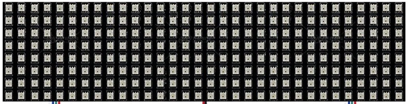
The WS2812 8x32 RGB Matrix FLEX PCB is a flexible LED matrix display consisting of 256 individually addressable RGB LEDs arranged in an 8x32 grid. Each LED is based on the WS2812 intelligent control chip, which allows for vibrant color displays and animations controlled via a single data line. The matrix is designed for flexibility, making it suitable for curved or irregular surfaces.
Explore Projects Built with WS2812 8x32 RGB Matrix


Explore Projects Built with WS2812 8x32 RGB Matrix
Common Applications and Use Cases
- LED displays for signage and advertising
- Dynamic lighting effects for events and stage design
- Wearable electronics and costumes
- DIY projects and hobbyist creations
- Interactive art installations
- Gaming and entertainment displays
Technical Specifications
Key Technical Details
| Parameter | Specification |
|---|---|
| Manufacturer | Generic |
| Part ID | WS2812 8x32 RGB Matrix FLEX PCB |
| LED Count | 256 (8 rows x 32 columns) |
| LED Type | WS2812 RGB LEDs (individually addressable) |
| Operating Voltage | 5V DC |
| Power Consumption | ~60mA per LED at full brightness (white) |
| Communication Protocol | Single-wire serial (WS2812 protocol) |
| Refresh Rate | ~400Hz |
| Dimensions | ~320mm x 80mm |
| PCB Type | Flexible |
Pin Configuration and Descriptions
| Pin Name | Description |
|---|---|
| VCC | Power supply input (5V DC) |
| GND | Ground connection |
| DIN | Data input for controlling the LEDs |
| DOUT | Data output for chaining additional WS2812 devices |
Usage Instructions
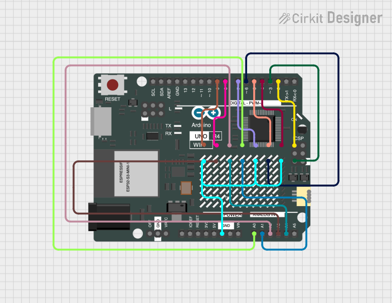
How to Use the Component in a Circuit
- Power Supply: Connect the VCC pin to a 5V DC power source and the GND pin to ground. Ensure the power supply can handle the current requirements of the matrix (up to ~15.4A at full brightness).
- Data Input: Connect the DIN pin to the data output pin of your microcontroller (e.g., Arduino, Raspberry Pi). Use a resistor (330-470Ω) in series with the data line to protect the LEDs.
- Capacitor: Place a 1000µF capacitor across the VCC and GND pins to stabilize the power supply.
- Chaining: If you need to connect multiple matrices, connect the DOUT pin of the first matrix to the DIN pin of the next.
Important Considerations and Best Practices
- Power Management: Avoid running all LEDs at full brightness for extended periods to prevent overheating and excessive power draw.
- Signal Integrity: Keep the data line as short as possible to avoid signal degradation. For longer distances, use a level shifter to ensure a 5V data signal.
- Heat Dissipation: Ensure adequate ventilation or heat dissipation, especially when running the matrix at high brightness levels.
- Code Libraries: Use libraries like Adafruit NeoPixel or FastLED for simplified control of the WS2812 LEDs.
Example Code for Arduino UNO
Below is an example of how to control the WS2812 8x32 RGB Matrix using the Adafruit NeoPixel library:
#include <Adafruit_NeoPixel.h>

// Define the number of LEDs in the matrix
#define NUM_LEDS 256

// Define the pin connected to the DIN pin of the matrix
#define DATA_PIN 6

// Create an instance of the Adafruit_NeoPixel library
Adafruit_NeoPixel matrix = Adafruit_NeoPixel(NUM_LEDS, DATA_PIN, NEO_GRB + NEO_KHZ800);

void setup() {
  matrix.begin(); // Initialize the matrix
  matrix.show();  // Turn off all LEDs initially
}

void loop() {
  // Example: Light up the matrix with a rainbow effect
  rainbowCycle(10); // Call the rainbowCycle function with a delay of 10ms
}

// Function to create a rainbow effect across the matrix
void rainbowCycle(uint8_t wait) {
  uint16_t i, j;

  for (j = 0; j < 256; j++) { // Cycle through all colors
    for (i = 0; i < matrix.numPixels(); i++) {
      matrix.setPixelColor(i, Wheel((i + j) & 255)); // Set pixel color
    }
    matrix.show(); // Update the matrix
    delay(wait);   // Wait for the specified delay
  }
}

// Helper function to generate rainbow colors
uint32_t Wheel(byte WheelPos) {
  WheelPos = 255 - WheelPos;
  if (WheelPos < 85) {
    return matrix.Color(255 - WheelPos * 3, 0, WheelPos * 3);
  } else if (WheelPos < 170) {
    WheelPos -= 85;
    return matrix.Color(0, WheelPos * 3, 255 - WheelPos * 3);
  } else {
    WheelPos -= 170;
    return matrix.Color(WheelPos * 3, 255 - WheelPos * 3, 0);
  }
}
Troubleshooting and FAQs
Common Issues and Solutions
No LEDs Lighting Up:
- Verify the power supply is providing 5V and sufficient current.
- Check all connections, especially the DIN pin.
- Ensure the microcontroller is properly programmed and the data pin is correctly defined.
Flickering or Incorrect Colors:
- Add a 330-470Ω resistor in series with the data line to reduce noise.
- Use a 1000µF capacitor across VCC and GND to stabilize the power supply.
- Ensure the data signal is at 5V logic level (use a level shifter if necessary).
Matrix Overheating:
- Reduce the brightness of the LEDs in your code.
- Avoid running all LEDs at full brightness for extended periods.
Data Signal Not Passing to Chained Matrices:
- Check the connection between the DOUT pin of the first matrix and the DIN pin of the next.
- Ensure the power supply is sufficient for all connected matrices.
FAQs
Q: Can I cut the matrix into smaller sections?
A: Yes, the matrix can be cut along the designated cut lines. Ensure you reconnect the VCC, GND, and data lines properly for the remaining sections.
Q: What is the maximum number of matrices I can chain together?
A: Theoretically, you can chain many matrices, but the practical limit depends on the microcontroller's memory and the power supply's capacity.
Q: Can I power the matrix directly from the Arduino?
A: No, the Arduino cannot supply enough current. Use an external 5V power supply capable of handling the matrix's current requirements.
Q: Is the matrix waterproof?
A: No, the WS2812 8x32 RGB Matrix FLEX PCB is not waterproof. Use a waterproof enclosure if needed for outdoor applications.