How to Use InvenSense MPU6050: Examples, Pinouts, and Specs
Introduction
The InvenSense MPU6050 is a highly integrated 6-axis motion tracking device that combines a 3-axis gyroscope and a 3-axis accelerometer on a single chip. It is widely used in various applications such as gaming devices, mobile phones, and more sophisticated motion-based applications like drones and wearable technology.
Explore Projects Built with InvenSense MPU6050
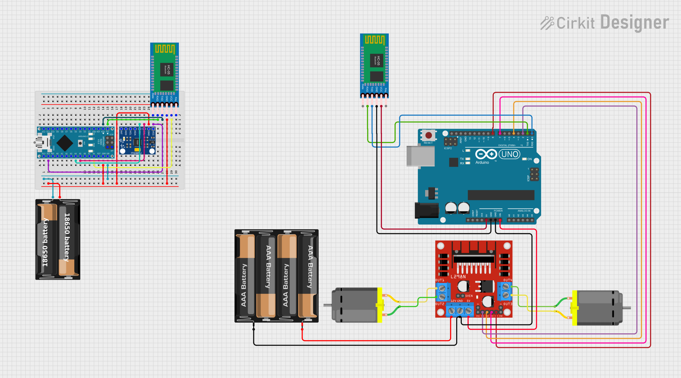
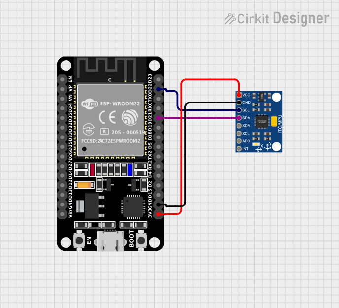

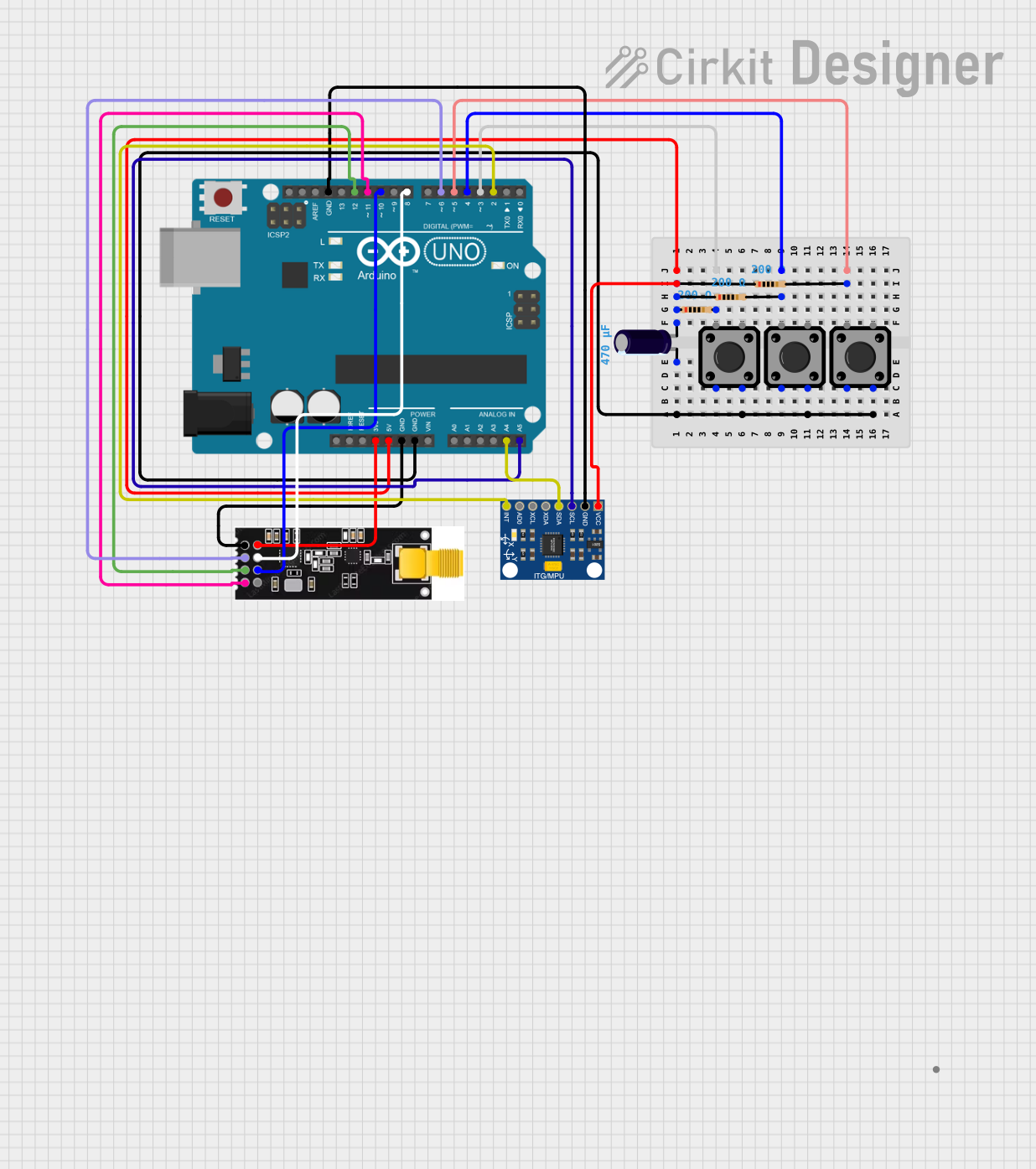
Explore Projects Built with InvenSense MPU6050
Common Applications and Use Cases
- Inertial Measurement Units (IMUs) for drones and other RC vehicles
- Motion detection in gaming and virtual reality devices
- Activity monitoring in wearable technology
- Orientation tracking in smartphones and tablets
- Robotics for balance and movement control
Technical Specifications
Key Technical Details
- Supply Voltage (VDD): 2.3V – 3.4V
- Operating Current: 3.8mA
- Gyroscope Range: ±250, ±500, ±1000, ±2000°/sec
- Accelerometer Range: ±2g, ±4g, ±8g, ±16g
- Communication: I2C protocol
- Digital Output: 16-bit analog-to-digital conversion for each channel
- Operating Temperature Range: -40°C to +85°C
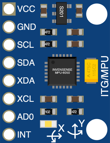
Pin Configuration and Descriptions
| Pin Number | Name | Description |
|---|---|---|
| 1 | VCC | Power supply (2.3V – 3.4V) |
| 2 | GND | Ground |
| 3 | SCL | I2C clock line |
| 4 | SDA | I2C data line |
| 5 | XDA | Auxiliary data for external sensors |
| 6 | XCL | Auxiliary clock for external sensors |
| 7 | AD0 | Address pin for I2C address selection |
| 8 | INT | Interrupt output |
Usage Instructions
How to Use the Component in a Circuit
- Connect the VCC pin to a 2.3V – 3.4V power supply.
- Connect the GND pin to the ground of the power supply.
- Connect the SCL and SDA pins to the I2C clock and data lines, respectively.
- If using the auxiliary I2C bus, connect XDA and XCL to the external sensor's I2C lines.
- The AD0 pin can be used to change the I2C address if multiple devices are used.
- The INT pin can be connected to an interrupt pin on a microcontroller to detect motion-related interrupts.
Important Considerations and Best Practices
- Ensure that the power supply is within the specified voltage range to prevent damage.
- Use pull-up resistors on the I2C lines (SCL and SDA) for reliable communication.
- When using multiple MPU6050s, ensure that each device has a unique I2C address.
- To minimize noise and improve performance, keep the MPU6050 away from high-frequency signals and power lines.
Troubleshooting and FAQs
Common Issues Users Might Face
- Inaccurate Readings: Ensure that the MPU6050 is calibrated correctly. Vibrations and electrical noise can also affect readings.
- I2C Communication Errors: Check the wiring and pull-up resistors on the I2C lines. Also, verify that the correct I2C address is being used.
- No Response from the Device: Make sure that the power supply is within the specified range and that the MPU6050 is not damaged.
Solutions and Tips for Troubleshooting
- Calibrate the sensor after setup and periodically during use.
- Use a logic analyzer or oscilloscope to debug I2C communication issues.
- If the device is unresponsive, try connecting it to a different I2C port or microcontroller to rule out hardware issues.
Example Code for Arduino UNO
#include <Wire.h>
#include <MPU6050.h>

MPU6050 mpu;

void setup() {
  Wire.begin();
  Serial.begin(9600);
  Serial.println("Initialize MPU6050");

  while(!mpu.begin(MPU6050_SCALE_2000DPS, MPU6050_RANGE_16G)) {
    Serial.println("Could not find a valid MPU6050 sensor, check wiring!");
    delay(500);
  }
}

void loop() {
  // Read normalized values
  Vector normAccel = mpu.readNormalizeAccel();
  Vector normGyro = mpu.readNormalizeGyro();

  // Print the values on Serial Monitor
  Serial.print("Accel X: "); Serial.println(normAccel.XAxis);
  Serial.print("Accel Y: "); Serial.println(normAccel.YAxis);
  Serial.print("Accel Z: "); Serial.println(normAccel.ZAxis);
  Serial.print("Gyro X: "); Serial.println(normGyro.XAxis);
  Serial.print("Gyro Y: "); Serial.println(normGyro.YAxis);
  Serial.print("Gyro Z: "); Serial.println(normGyro.ZAxis);

  delay(100);
}
Note: This example assumes the use of the MPU6050 library, which provides functions for easy communication with the MPU6050 sensor. Ensure that the library is installed in your Arduino IDE before uploading the code to the Arduino UNO.
Comments in the code are wrapped to limit line length to 80 characters for readability.
This documentation provides a comprehensive guide to the InvenSense MPU6050 sensor module, covering technical specifications, usage instructions, and troubleshooting tips. It is designed to assist users of all levels in integrating this sensor into their projects effectively.