How to Use LM25965 DC-DC Step Down Power Supply: Examples, Pinouts, and Specs
Introduction
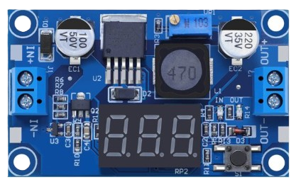
The LM25965 is a high-efficiency, step-down (buck) voltage regulator designed to convert a higher input voltage to a stable, lower output voltage. This component is ideal for applications requiring efficient power conversion, such as powering microcontrollers, sensors, and other electronic devices. Its compact design and robust performance make it a popular choice for embedded systems, industrial equipment, and consumer electronics.
Explore Projects Built with LM25965 DC-DC Step Down Power Supply


Explore Projects Built with LM25965 DC-DC Step Down Power Supply
Common Applications
- Powering microcontrollers and development boards (e.g., Arduino, Raspberry Pi)
- Battery-powered devices
- Industrial automation systems
- Consumer electronics
- LED drivers and lighting systems
Technical Specifications
The LM25965 is designed to deliver reliable performance under a wide range of operating conditions. Below are its key technical specifications:
| Parameter | Value |
|---|---|
| Input Voltage Range | 4.5V to 40V |
| Output Voltage Range | Adjustable (1.2V to 37V) |
| Output Current | Up to 5A |
| Efficiency | Up to 90% (depending on input/output ratio) |
| Switching Frequency | 150 kHz |
| Operating Temperature | -40°C to +125°C |
| Package Type | TO-220-5 or TO-263-5 |
Pin Configuration and Descriptions
The LM25965 typically comes in a 5-pin package. Below is the pinout and description:
| Pin Number | Pin Name | Description |
|---|---|---|
| 1 | VIN | Input voltage pin. Connect to the positive terminal of the input power source. |
| 2 | GND | Ground pin. Connect to the negative terminal of the input power source. |
| 3 | VOUT | Output voltage pin. Provides the regulated output voltage. |
| 4 | FB | Feedback pin. Used to set the output voltage via an external resistor divider. |
| 5 | ON/OFF | Enable pin. Pull high to enable the regulator, or low to disable it. |
Usage Instructions
How to Use the LM25965 in a Circuit
- Input Voltage: Ensure the input voltage (VIN) is within the range of 4.5V to 40V.
- Output Voltage Adjustment: Use a resistor divider network connected to the FB pin to set the desired output voltage. The output voltage can be calculated using the formula: [ V_{OUT} = V_{REF} \times \left(1 + \frac{R1}{R2}\right) ] where ( V_{REF} ) is typically 1.2V.
- Capacitors: Add input and output capacitors to stabilize the circuit. A 100 µF capacitor is commonly used on both the input and output.
- Inductor Selection: Choose an inductor with a suitable current rating and inductance value to ensure efficient operation.
- Enable Pin: Connect the ON/OFF pin to VIN (or a logic high signal) to enable the regulator. Pull it to GND to disable it.
Example Circuit
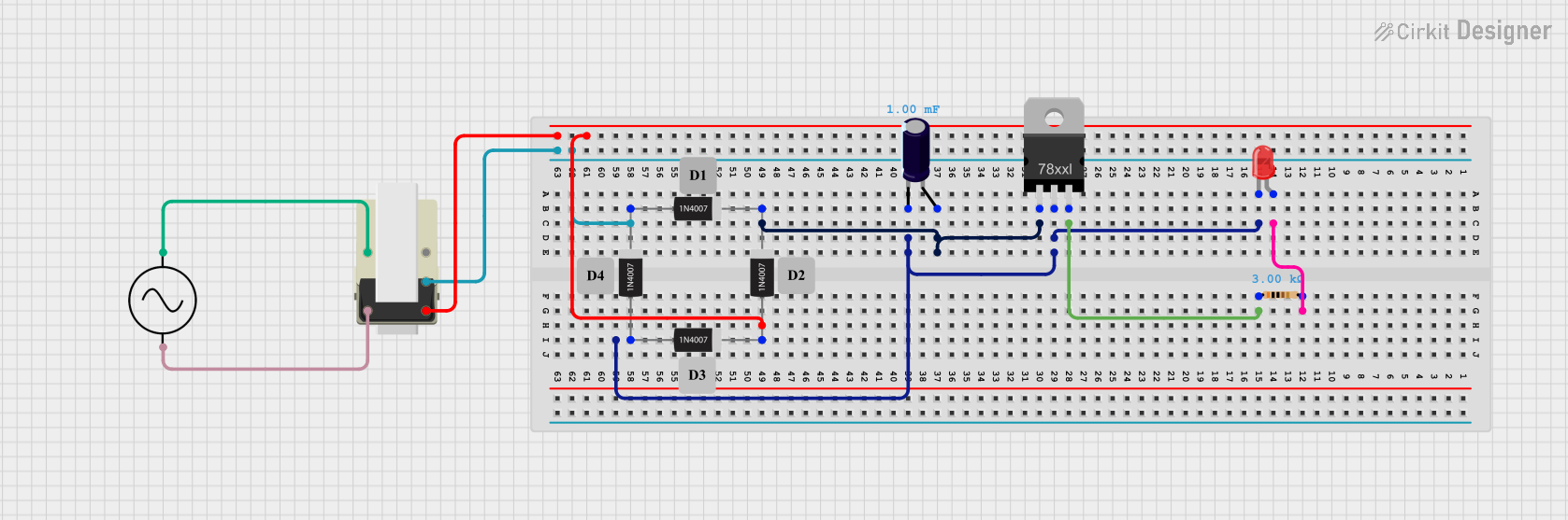
Below is a basic circuit diagram for using the LM25965:
VIN ----+----[Input Capacitor]----+---- LM25965 ----+----[Output Capacitor]---- VOUT
        |                        |                 |                          |
       GND                      GND               GND                        GND
Using LM25965 with Arduino UNO
The LM25965 can be used to power an Arduino UNO by stepping down a higher voltage (e.g., 12V) to 5V. Connect the output of the LM25965 to the Arduino's 5V pin and GND.
Example Code for Arduino
If the LM25965 is used to power sensors or peripherals, you can use the following Arduino code to read sensor data:
// Example: Reading data from a sensor powered by LM25965
const int sensorPin = A0; // Analog pin connected to the sensor output
int sensorValue = 0;     // Variable to store the sensor reading

void setup() {
  Serial.begin(9600); // Initialize serial communication
  pinMode(sensorPin, INPUT); // Set the sensor pin as input
}

void loop() {
  sensorValue = analogRead(sensorPin); // Read the sensor value
  Serial.print("Sensor Value: ");
  Serial.println(sensorValue); // Print the sensor value to the Serial Monitor
  delay(1000); // Wait for 1 second before the next reading
}
Important Considerations
- Heat Dissipation: The LM25965 can generate heat during operation. Use a heatsink or ensure proper ventilation to prevent overheating.
- Input Voltage: Always ensure the input voltage is higher than the desired output voltage.
- Inductor and Capacitor Selection: Use components with appropriate ratings to ensure stable operation and avoid damage.
Troubleshooting and FAQs
Common Issues and Solutions
No Output Voltage
- Cause: The ON/OFF pin is not properly connected.
- Solution: Ensure the ON/OFF pin is pulled high to enable the regulator.
Output Voltage is Unstable
- Cause: Insufficient input or output capacitance.
- Solution: Add or replace capacitors with higher capacitance values.
Excessive Heat
- Cause: High input voltage or insufficient cooling.
- Solution: Use a heatsink or reduce the input voltage if possible.
Incorrect Output Voltage
- Cause: Incorrect resistor values in the feedback network.
- Solution: Verify and adjust the resistor values to achieve the desired output voltage.
FAQs
Q: Can the LM25965 be used with a 3.3V system?
A: Yes, the LM25965 can be configured to output 3.3V by adjusting the feedback resistor network.
Q: What is the maximum current the LM25965 can handle?
A: The LM25965 can handle up to 5A of output current, provided proper cooling is implemented.
Q: Can I use the LM25965 to power an Arduino directly?
A: Yes, you can use the LM25965 to step down a higher voltage (e.g., 12V) to 5V and connect it to the Arduino's 5V pin.
Q: How do I calculate the inductor value for my circuit?
A: The inductor value depends on the input voltage, output voltage, and switching frequency. Refer to the LM25965 datasheet for detailed calculations.
By following this documentation, you can effectively integrate the LM25965 DC-DC Step Down Power Supply into your projects for efficient and reliable power regulation.