How to Use esp32 c3: Examples, Pinouts, and Specs
Introduction
The ESP32-C3, manufactured by Espressif, is a low-power system-on-a-chip (SoC) designed for Internet of Things (IoT) applications. It features a RISC-V single-core processor, integrated Wi-Fi (2.4 GHz), and Bluetooth Low Energy (BLE) 5.0 capabilities. The ESP32-C3 is engineered for high performance, energy efficiency, and robust connectivity, making it an excellent choice for smart devices, sensor networks, and other IoT solutions.
Explore Projects Built with esp32 c3


Explore Projects Built with esp32 c3
Common Applications and Use Cases
- Smart home devices (e.g., smart plugs, lights, and thermostats)
- Wearable devices with BLE connectivity
- Industrial IoT systems and sensor networks
- Wireless data logging and monitoring
- Low-power, battery-operated devices
- Secure IoT applications with hardware encryption support
Technical Specifications
The ESP32-C3 offers a range of features and capabilities that make it versatile for various applications. Below are its key technical specifications:
General Specifications
| Feature | Description |
|---|---|
| Processor | RISC-V single-core, 32-bit, up to 160 MHz |
| Wireless Connectivity | Wi-Fi 4 (802.11 b/g/n, 2.4 GHz), Bluetooth 5.0 (LE) |
| Flash Memory | Up to 4 MB embedded flash |
| SRAM | 400 KB (16 KB RTC fast memory, 8 KB RTC slow memory) |
| GPIO Pins | 22 GPIOs with multiple functions |
| Operating Voltage | 3.0V to 3.6V |
| Power Consumption | Ultra-low power modes supported |
| Security Features | AES-128/256, SHA-256, RSA, HMAC, Digital Signature, Secure Boot, Flash Encryption |
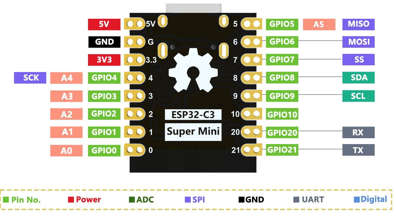
Pin Configuration and Descriptions
The ESP32-C3 is available in various packages, such as the ESP32-C3-WROOM-02 module. Below is the pin configuration for the module:
| Pin Number | Pin Name | Function |
|---|---|---|
| 1 | GND | Ground |
| 2 | 3V3 | Power supply (3.3V) |
| 3 | EN | Chip enable (active high) |
| 4 | IO0 | GPIO0, supports ADC, UART, PWM, and other functions |
| 5 | IO1 | GPIO1, supports ADC, UART, PWM, and other functions |
| 6 | IO2 | GPIO2, supports ADC, UART, PWM, and other functions |
| 7 | IO3 | GPIO3, supports ADC, UART, PWM, and other functions |
| 8 | IO4 | GPIO4, supports ADC, UART, PWM, and other functions |
| 9 | IO5 | GPIO5, supports ADC, UART, PWM, and other functions |
| 10 | RXD | UART RX (serial input) |
| 11 | TXD | UART TX (serial output) |
| 12 | IO6 | GPIO6, supports ADC, UART, PWM, and other functions |
| 13 | IO7 | GPIO7, supports ADC, UART, PWM, and other functions |
| 14 | IO8 | GPIO8, supports ADC, UART, PWM, and other functions |
| 15 | IO9 | GPIO9, supports ADC, UART, PWM, and other functions |
| 16 | IO10 | GPIO10, supports ADC, UART, PWM, and other functions |
| 17 | IO11 | GPIO11, supports ADC, UART, PWM, and other functions |
| 18 | IO12 | GPIO12, supports ADC, UART, PWM, and other functions |
| 19 | IO13 | GPIO13, supports ADC, UART, PWM, and other functions |
| 20 | IO14 | GPIO14, supports ADC, UART, PWM, and other functions |
| 21 | IO15 | GPIO15, supports ADC, UART, PWM, and other functions |
| 22 | IO16 | GPIO16, supports ADC, UART, PWM, and other functions |
Usage Instructions
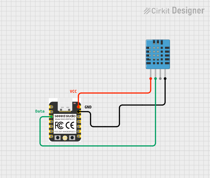
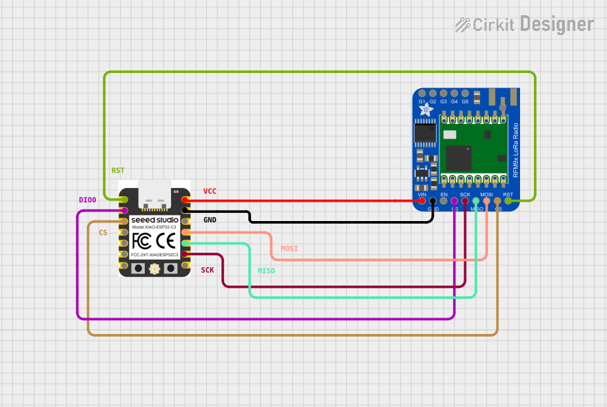
How to Use the ESP32-C3 in a Circuit
- Power Supply: Provide a stable 3.3V power supply to the
3V3pin. Ensure the ground (GND) is connected to the circuit's ground. - Programming: Use a USB-to-UART adapter to connect the ESP32-C3 to your computer. Connect the RXD and TXD pins to the adapter's TX and RX pins, respectively.
- Boot Mode: To upload code, hold the
IO0pin low (connect to GND) while resetting the chip. - GPIO Usage: Configure GPIO pins for input or output as needed. Many GPIOs support additional functions like ADC, PWM, and UART.
- Antenna: Ensure the onboard antenna has sufficient clearance from metal objects to avoid interference.
Important Considerations and Best Practices
- Power Supply: Use a low-noise, stable power source to avoid issues with Wi-Fi and BLE performance.
- GPIO Voltage: All GPIOs are 3.3V logic level. Avoid applying higher voltages to prevent damage.
- Antenna Placement: For optimal wireless performance, keep the antenna area free from obstructions.
- Firmware Updates: Regularly update the firmware to benefit from the latest features and security patches.
Example Code for Arduino UNO
The ESP32-C3 can be programmed using the Arduino IDE. Below is an example of a simple Wi-Fi connection script:
#include <WiFi.h> // Include the Wi-Fi library for ESP32-C3

// Replace with your network credentials
const char* ssid = "Your_SSID";
const char* password = "Your_PASSWORD";

void setup() {
  Serial.begin(115200); // Initialize serial communication at 115200 baud
  delay(1000); // Wait for a second to stabilize the serial monitor

  Serial.println("Connecting to Wi-Fi...");
  WiFi.begin(ssid, password); // Start Wi-Fi connection

  // Wait until the ESP32-C3 connects to the Wi-Fi network
  while (WiFi.status() != WL_CONNECTED) {
    delay(500);
    Serial.print(".");
  }

  Serial.println("\nConnected to Wi-Fi!");
  Serial.print("IP Address: ");
  Serial.println(WiFi.localIP()); // Print the assigned IP address
}

void loop() {
  // Add your main code here
}
Troubleshooting and FAQs
Common Issues and Solutions
- ESP32-C3 Not Connecting to Wi-Fi
- Solution: Double-check the SSID and password. Ensure the router is within range and supports 2.4 GHz Wi-Fi.
- Code Upload Fails
- Solution: Ensure the
IO0pin is held low during reset to enter boot mode. Verify the USB-to-UART adapter is properly connected.
- Solution: Ensure the
- Unstable Power Supply
- Solution: Use a capacitor (e.g., 10 µF) across the power supply pins to stabilize voltage.
- GPIO Not Responding
- Solution: Verify the GPIO pin configuration in your code. Ensure no conflicting functions are assigned to the same pin.
FAQs
Q: Can the ESP32-C3 operate on 5V?
A: No, the ESP32-C3 operates on 3.3V. Applying 5V to GPIOs or power pins may damage the chip.Q: Does the ESP32-C3 support OTA updates?
A: Yes, the ESP32-C3 supports Over-The-Air (OTA) firmware updates.Q: How do I reset the ESP32-C3?
A: Press theENpin or button to reset the chip.Q: Can I use the ESP32-C3 for battery-powered applications?
A: Yes, the ESP32-C3 is designed for low-power applications and supports deep sleep modes.