How to Use Grove-IMU: Examples, Pinouts, and Specs
Introduction
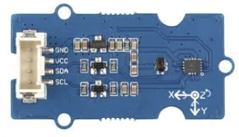
The Grove-IMU (Manufacturer Part ID: lcm20600+AK09918) is a high-performance Inertial Measurement Unit (IMU) developed by Seeed Studio. It integrates a 3-axis accelerometer, a 3-axis gyroscope, and a 3-axis magnetometer into a single module, enabling precise orientation and motion sensing. This compact and versatile sensor is ideal for applications such as robotics, drones, wearable devices, gaming controllers, and navigation systems.
The Grove-IMU is part of the Grove ecosystem, which simplifies prototyping and development by providing standardized connectors and plug-and-play functionality. It communicates with microcontrollers via the I2C interface, making it compatible with popular development platforms like Arduino, Raspberry Pi, and others.
Explore Projects Built with Grove-IMU


Explore Projects Built with Grove-IMU
Technical Specifications
Below are the key technical details of the Grove-IMU:
| Parameter | Value |
|---|---|
| Manufacturer | Seeed Studio |
| Part ID | lcm20600+AK09918 |
| Sensor Components | 3-axis accelerometer, 3-axis gyroscope, 3-axis magnetometer |
| Communication Interface | I2C |
| Operating Voltage | 3.3V to 5V |
| Operating Current | ~5mA |
| Accelerometer Range | ±2g, ±4g, ±8g, ±16g |
| Gyroscope Range | ±250°/s, ±500°/s, ±1000°/s, ±2000°/s |
| Magnetometer Range | ±4900µT |
| Operating Temperature | -40°C to +85°C |
| Dimensions | 20mm x 40mm |
Pin Configuration
The Grove-IMU module features a standard 4-pin Grove connector. The pinout is as follows:
| Pin | Name | Description |
|---|---|---|
| 1 | VCC | Power supply (3.3V to 5V) |
| 2 | GND | Ground |
| 3 | SDA | I2C data line |
| 4 | SCL | I2C clock line |
Usage Instructions
Connecting the Grove-IMU to an Arduino UNO
Hardware Setup:
- Connect the Grove-IMU to the I2C port of the Grove Base Shield.
- Attach the Grove Base Shield to the Arduino UNO.
- Ensure the Arduino is powered via USB or an external power source.
Install Required Libraries:
- Download and install the
Seeed_Arduino_LSM6DS3andSeeed_Arduino_AK09918libraries from the Arduino Library Manager.
- Download and install the
Example Code: Below is an example Arduino sketch to read accelerometer, gyroscope, and magnetometer data from the Grove-IMU:
#include <Wire.h>
#include "LSM6DS3.h"  // Library for accelerometer and gyroscope
#include "AK09918.h"  // Library for magnetometer

LSM6DS3 imu;  // Create an instance of the LSM6DS3 class
AK09918 mag;  // Create an instance of the AK09918 class

void setup() {
  Serial.begin(9600);  // Initialize serial communication
  Wire.begin();        // Initialize I2C communication

  // Initialize the accelerometer and gyroscope
  if (!imu.begin()) {
    Serial.println("Failed to initialize LSM6DS3!");
    while (1);  // Halt execution if initialization fails
  }

  // Initialize the magnetometer
  if (!mag.begin()) {
    Serial.println("Failed to initialize AK09918!");
    while (1);  // Halt execution if initialization fails
  }

  Serial.println("Grove-IMU initialized successfully!");
}

void loop() {
  // Read accelerometer data
  float ax = imu.readFloatAccelX();
  float ay = imu.readFloatAccelY();
  float az = imu.readFloatAccelZ();

  // Read gyroscope data
  float gx = imu.readFloatGyroX();
  float gy = imu.readFloatGyroY();
  float gz = imu.readFloatGyroZ();

  // Read magnetometer data
  float mx = mag.readMagX();
  float my = mag.readMagY();
  float mz = mag.readMagZ();

  // Print sensor data to the Serial Monitor
  Serial.print("Accel (g): X=");
  Serial.print(ax, 2);
  Serial.print(" Y=");
  Serial.print(ay, 2);
  Serial.print(" Z=");
  Serial.println(az, 2);

  Serial.print("Gyro (°/s): X=");
  Serial.print(gx, 2);
  Serial.print(" Y=");
  Serial.print(gy, 2);
  Serial.print(" Z=");
  Serial.println(gz, 2);

  Serial.print("Mag (µT): X=");
  Serial.print(mx, 2);
  Serial.print(" Y=");
  Serial.print(my, 2);
  Serial.print(" Z=");
  Serial.println(mz, 2);

  Serial.println("-----------------------------");
  delay(500);  // Wait for 500ms before the next reading
}
Important Considerations
- Ensure the Grove-IMU is connected to the correct I2C port on the Grove Base Shield.
- Use pull-up resistors on the I2C lines if the microcontroller does not have internal pull-ups enabled.
- Avoid placing the sensor near strong magnetic fields or vibrations, as they may affect accuracy.
Troubleshooting and FAQs
Common Issues
The sensor is not detected:
- Ensure the Grove-IMU is properly connected to the I2C port.
- Verify that the correct I2C address is being used in the code (default:
0x6Afor LSM6DS3 and0x0Cfor AK09918). - Check the wiring and ensure the power supply voltage is within the specified range.
Incorrect or unstable readings:
- Ensure the sensor is mounted securely to avoid vibrations.
- Calibrate the sensor if necessary, especially for the magnetometer.
Library installation errors:
- Ensure the required libraries (
Seeed_Arduino_LSM6DS3andSeeed_Arduino_AK09918) are installed correctly via the Arduino Library Manager.
- Ensure the required libraries (
FAQs
Q: Can the Grove-IMU be used with a Raspberry Pi?
A: Yes, the Grove-IMU can be used with a Raspberry Pi via the I2C interface. You may need to use Python libraries such as smbus to communicate with the sensor.
Q: How do I calibrate the magnetometer?
A: Calibration involves rotating the sensor in all directions to collect data for offset and scaling adjustments. Refer to the AK09918 datasheet or library documentation for detailed calibration procedures.
Q: What is the maximum sampling rate of the sensor?
A: The LSM6DS3 supports a maximum output data rate (ODR) of 1.66 kHz for the accelerometer and gyroscope. The AK09918 magnetometer supports an ODR of up to 100 Hz.