How to Use VFD: Examples, Pinouts, and Specs
Introduction
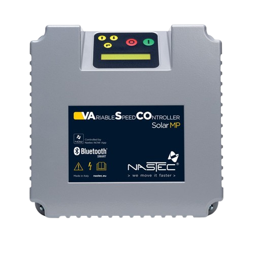
A Variable Frequency Drive (VFD), such as the Nastec 3P VFD, is an electronic device designed to control the speed and torque of an electric motor. It achieves this by varying the frequency and voltage of the power supplied to the motor. This capability makes VFDs essential for applications requiring precise motor control, energy efficiency, and reduced mechanical stress.
Explore Projects Built with VFD
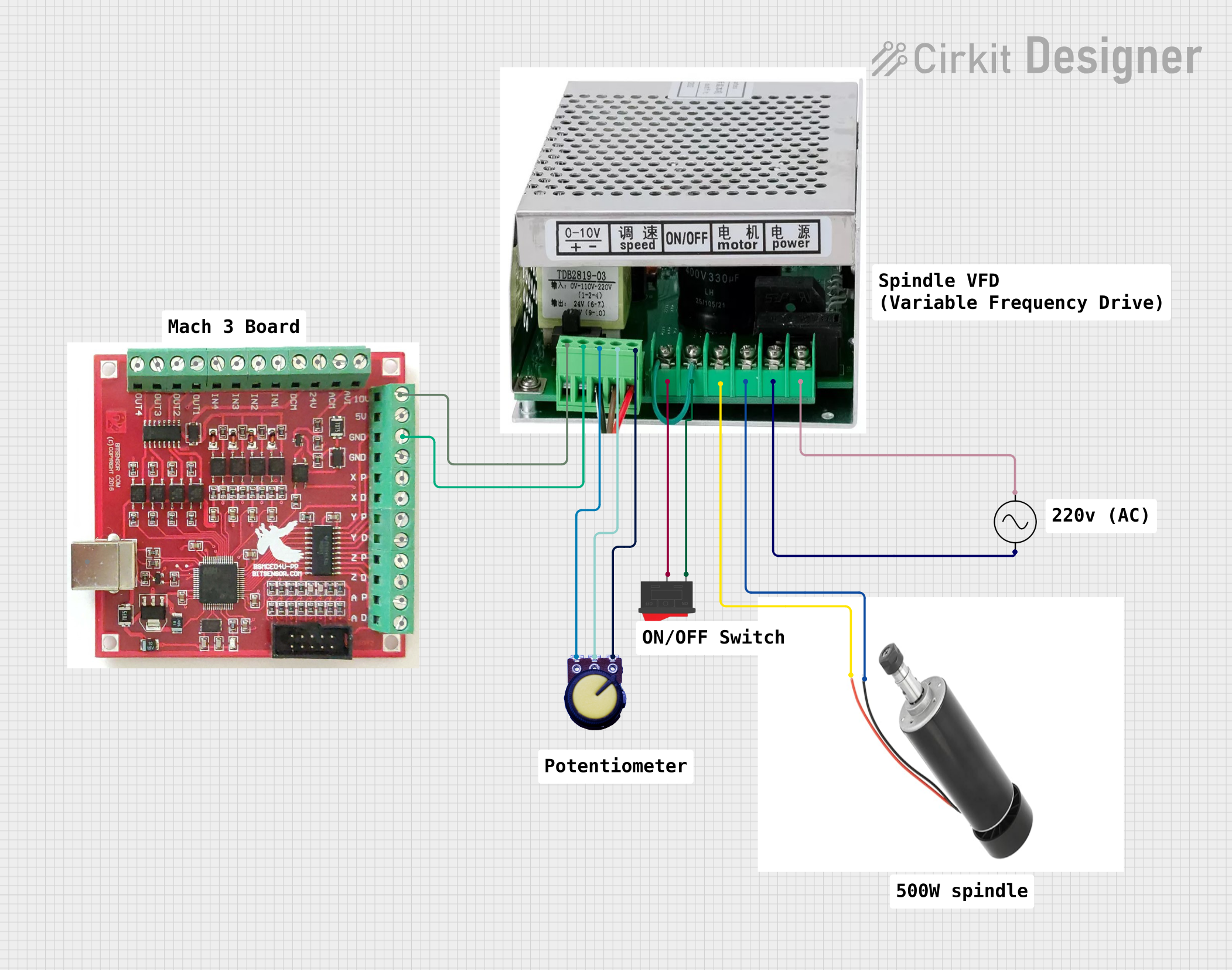


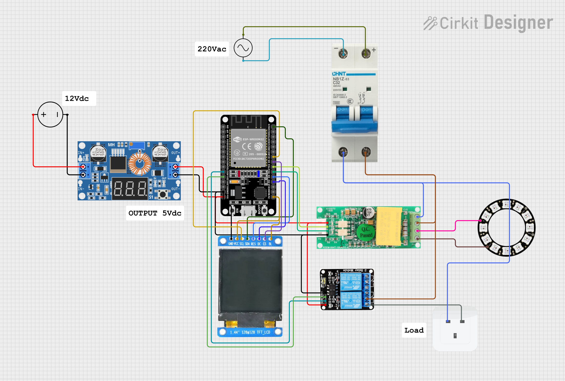
Explore Projects Built with VFD
Common Applications and Use Cases
- Industrial Automation: Controlling conveyor belts, pumps, and fans.
- HVAC Systems: Regulating air flow and temperature.
- Energy Efficiency: Reducing power consumption in motor-driven systems.
- Agriculture: Managing irrigation pumps and other motorized equipment.
- Elevators and Escalators: Smooth acceleration and deceleration of motors.
Technical Specifications
The Nastec 3P VFD is a robust and versatile device. Below are its key technical details:
General Specifications
| Parameter | Value |
|---|---|
| Manufacturer | Nastec |
| Part ID | 3P VFD |
| Input Voltage Range | 200V - 480V AC |
| Output Voltage Range | 0V - Input Voltage |
| Frequency Range | 0 Hz - 400 Hz |
| Power Rating | 0.75 kW - 22 kW (varies by model) |
| Control Method | V/F (Voltage/Frequency) Control, Vector Control |
| Efficiency | ≥ 98% |
| Operating Temperature | -10°C to 50°C |
| Protection Rating | IP20 (standard), optional IP55 |
Pin Configuration and Descriptions
The Nastec 3P VFD features a terminal block for input/output connections. Below is the pin configuration:
Power Terminals
| Pin Label | Description |
|---|---|
| R/L1 | AC Input Phase 1 |
| S/L2 | AC Input Phase 2 |
| T/L3 | AC Input Phase 3 |
| U/T1 | Motor Output Phase 1 |
| V/T2 | Motor Output Phase 2 |
| W/T3 | Motor Output Phase 3 |
Control Terminals
| Pin Label | Description |
|---|---|
| +10V | 10V Reference Voltage Output |
| AI1 | Analog Input 1 (0-10V or 4-20mA) |
| DI1 | Digital Input 1 (Start/Stop) |
| DI2 | Digital Input 2 (Direction Control) |
| AO1 | Analog Output 1 (0-10V) |
| COM | Common Ground |
Usage Instructions
How to Use the Nastec 3P VFD in a Circuit
Power Connection:
- Connect the AC input phases (R/L1, S/L2, T/L3) to the power supply.
- Connect the motor phases (U/T1, V/T2, W/T3) to the motor terminals.
Control Wiring:
- Use the control terminals to connect external devices like potentiometers, switches, or PLCs.
- For speed control, connect a potentiometer to the +10V, AI1, and COM terminals.
Programming:
- Use the built-in keypad or software interface to configure parameters such as motor type, frequency range, and acceleration/deceleration times.
Startup:
- Ensure all connections are secure and power on the VFD.
- Set the desired frequency using the keypad or external control device.
- Start the motor using the configured digital input (e.g., DI1).
Important Considerations and Best Practices
- Motor Compatibility: Ensure the motor's voltage and current ratings match the VFD's output specifications.
- Grounding: Properly ground the VFD to prevent electrical noise and ensure safety.
- Cooling: Install the VFD in a well-ventilated area to prevent overheating.
- EMI Shielding: Use shielded cables for motor connections to minimize electromagnetic interference.
- Parameter Settings: Double-check all parameter settings before starting the motor to avoid damage.
Example: Connecting to an Arduino UNO
The Nastec 3P VFD can be controlled using an Arduino UNO via its digital and analog inputs. Below is an example code to control motor speed using PWM:
// Define the PWM pin connected to the VFD's AI1 terminal
const int pwmPin = 9;

void setup() {
  // Set the PWM pin as output
  pinMode(pwmPin, OUTPUT);
}

void loop() {
  // Generate a PWM signal to control motor speed
  // Speed range: 0 (stopped) to 255 (full speed)
  for (int speed = 0; speed <= 255; speed += 5) {
    analogWrite(pwmPin, speed); // Write PWM signal to AI1
    delay(100); // Wait for 100ms before increasing speed
  }

  // Gradually decrease speed
  for (int speed = 255; speed >= 0; speed -= 5) {
    analogWrite(pwmPin, speed); // Write PWM signal to AI1
    delay(100); // Wait for 100ms before decreasing speed
  }
}
Troubleshooting and FAQs
Common Issues and Solutions
Motor Does Not Start:
- Cause: Incorrect wiring or parameter settings.
- Solution: Verify all connections and ensure the start command is properly configured.
Overheating:
- Cause: Poor ventilation or excessive load.
- Solution: Improve airflow around the VFD and ensure the motor is not overloaded.
Noise or Vibration in Motor:
- Cause: Incorrect frequency settings or motor misalignment.
- Solution: Adjust the frequency parameters and check motor alignment.
Fault Codes on Display:
- Cause: Various issues such as overvoltage, undervoltage, or short circuit.
- Solution: Refer to the Nastec 3P VFD user manual for specific fault code meanings and corrective actions.
FAQs
Q: Can the VFD be used with single-phase motors?
- A: The Nastec 3P VFD is designed for three-phase motors. For single-phase motors, consult the manufacturer for compatibility.
Q: How do I reset the VFD to factory settings?
- A: Use the keypad menu to navigate to the reset option or consult the user manual for detailed instructions.
Q: What type of cable should I use for motor connections?
- A: Use shielded cables to minimize electromagnetic interference and ensure reliable operation.
This concludes the documentation for the Nastec 3P VFD. For further assistance, refer to the official user manual or contact Nastec support.